
Owner's manual


5. SCON-CA
CC-Link
164
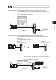
x PLC Output o SCON-CA Input (* “n” shows the head register address per each axis).
SCON-CA DI and Input data register
Position/Simplified
Direct Value Mode 2
Half Direct Value
Mode 2
Remote I/O mode 3
Half Direct Value
Mode 3
PLC address
Number of occupied
stations: 1 Station
Number of occupied
stations: 2 Stations
Number of occupied
stations: 1 Station
Number of occupied
stations: 2 Stations
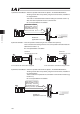
RY n0 – nF Occupied Area Port No.0 – 15
RY
(n+1)0 – (n+1)F
System Area System Area
RY
(n+2)0 – (n+2)F
Occupied Area Occupied Area
RY
(n+3)0 – (n+3)F
System Area System Area
RY
(n+4)0 – (n+4)F
RY
(n+5)0 – (n+5)F
RY
(n+6)0 – (n+6)F
RY
(n+7)0 – (n+7)F
RWw (n+0)
RWw (n+1)
Target Position Target Position Target Position
RWw (n+2)
Command position
number
RWw (n+3) Control Signal
Positioning Width
Occupied Area
Positioning Width
RWw (n+4) Speed Speed
RWw (n+5)
Acceleration/
Deceleration
Acceleration/
Deceleration
RWw (n+6)
Pressing Current
Limit Value
Pressing Current
Limit Value
RWw (n+7) Control signal Control signal
RWw (n+8)
RWw (n+9)
RWw (n+A)
RWw (n+B)
RWw (n+C)
RWw (n+D)
RWw (n+E)
RWw (n+F)
Note: The Occupied Area stands for the area occupied by means of the setting of the number of remote device
stations.
The System Area stands for the system area of the remote device station.
These areas are not used for any other purpose. Also take care about duplicating the use of the data register.