
Owner's manual


5. SCON-CA
CC-Link
160
5.3 CC-Link Interface
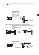
(1) Names of Each Section
The names of each section related to CC-Link are described as follows.
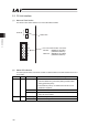
(2) Status LED Indication
The board operation status and network condition are obtained with the two LEDs located in the front of
the controller.
LED Color Indication Status Indication Description (Meaning)
Illuminating x An error occurs.
(CRC Error/Station No. (parameters) Setting Error/Baud Rate
Setting (parameters) Error)
x Period between power up or software reset and the CC-Link
initialization completion
OFF x Under Normal Communication
STATUS1 OR
Flashing x Station No. setting or communication speed setting is changed
during the communication.
Illuminating x Communicating normally STATUS0 GN
OFF x Not communicating
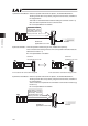
Status LED
CC-Link Communication Connector
1
STATUS
0
FG
SLD
DG
DB
DA
PCB side : MSTBA2.5/5-G-5.08AU
(PHOENIX CONTACT)
Cable side : SMSTB2.5/5-ST-5.08AU
(PHOENIX CONTACT)