
Instruction Manual

4. SCON-CA
88
4.3 PROFIBUS-DP (Slave Station) Settings
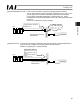
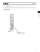
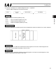
(1) Name of each part
The name of each part relating to PROFIBUS-DP is shown.
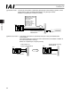
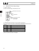
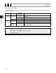
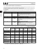
(2) PROFIBUS-DP communication connector interface specifications
This is a 9-pin, female D-sub connector recommended by the PROFIBUS-DP standard EN 50170.
Connector
Pin No. Description Contents
3 B-Line RxD, TxD (Positive signal line)
4 RTS Request to send
5 GND Signal ground (isolation)
6 +5V +5-V output (isolation)
8 A-Line /RxD, /TxD (Negative signal line)
Housing Shield Cable shield (enclosure and connection)
(Note 1) Pins 1, 2, 7 and 9 are not used (they need not be wired).
(Note 2) The cable-end connector is not supplied.
SV/ALM Status Indicator LEDs
NS
MS
Status LED
PROFIBUS communication connector
PCB side : D-sub Connector
(9-pin, female)