
Instruction Manual

5. Flow and Commands of Basic MECHATROLINK Communication
167
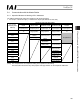
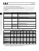
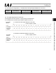
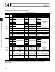
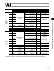
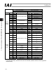
x SCON-CA output o PLC input (* n indicates the initial input address for each axis.)
SCON-CA DO and output data resister
Remote I/O mode
Position/simple
direct mode
Half direct mode Full direct mode Remote I/O mode 2
PLC input
address
(word address)
Number of occupied
bytes: 2
Number of
occupied bytes: 8
Number of
occupied bytes: 16
Number of
occupied bytes: 32
Number of
occupied bytes: 12
n
Port number 0 to 15 Port number 0 to 15
n+1
Current position Current position Current position
Occupied area
n+2
Completed position
number (simple
alarm ID
n+3
Status signal
Command current Command current Current position
n+4
n+5
Current speed Current speed Command current
n+6
Alarm code Alarm code
n+7
Status signal Occupied area
n+8
n+9
Force feedback
data
n+10
n+11
Total moving
count
n+12
n+13
Total moving
distance
n+14
Status signal 1
n+15
Status signal 2
(Note) The “occupied area” is occupied according to the operation mode setting.
This area cannot be used for any other purpose. Also pay attention to use of duplicate addresses.