
Instruction Manual

5. Flow and Commands of Basic MECHATROLINK Communication
165
5.4 Communication with the Master Station
5.4.1 Operation Modes and Handling of PLC Addresses
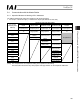
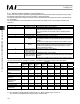
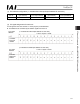
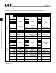
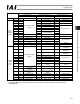
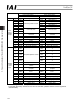
The address assignments under each operation mode are shown below.
x PLC output o SCON-CA input (* n indicates the output input address for each axis.)
SCON-CA and input data resister
Remote I/O
mode
Position/simple
direct mode
Half direct mode Full direct mode
Remote I/O
mode 2
PLC output
address (word
address)
Number of
occupied bytes: 2
Number of
occupied bytes: 8
Number of
occupied bytes: 16
Number of
occupied bytes: 32
Number of
occupied bytes: 12
n
Port number 0 to
15
Port number 0 to
15
n+1
Target position Target position Target position
n+2
Specified position
number
n+3
Control signal
Positioning band Positioning band
n+4
Speed
n+5
Acceleration/
deceleration
Speed
specification
Occupied area
n+6
Push-current
limiting value
n+7
Control signal
Zone boundary+
n+8
n+9
Zone boundary-
n+10
Acceleration
n+11
Deceleration
n+12
Push-current
limiting value
n+13
Load current
threshold
n+14
Control signal 1
n+15
Control signal 2
(Note) The “occupied area” is occupied according to the operation mode setting.
This area cannot be used for any other purpose. Also pay attention to use of duplicate addresses.