
User guide


10. Coordinate System Denition Data Edit Window
145
45°
45
35
0
01
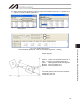
(1) Setting of tool coordinate system
Set the offsets from the center of tool installation surface to the tool end.
x Setting example of tool coordinate system
When defining tool coordinate system No. 1 as illustrated below:
Set the offsets for tool coordinate system No. 1 as Xoft1 = 45, Yoft1 = 35, Zoft1 = -10 and Roft1 =45.
Shown below is the tool coordinate system definition data edit screen when tool coordinate system No. 1
is set.
Fig. 10.7 Tool Coordinate System Offset Setting Screen
Fig. 10.8 Tool Coordinate System Offset Setting Screen (X-SEL-RXD/SXD)
* Use the DFTL instruction to set the tool coordinate system offsets in the SEL program