
User guide


10. Coordinate System Denition Data Edit Window
144
Rtn
n
t
X
n
t
Y
Roftn
Xoftn
Yoftn
Zoftn
Ztn
R-axis
Tool
Tool end
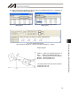
Xoftn: X tool coordinate offset
Yoftn: Y tool coordinate offset
Zoftn: Z tool coordinate offset
Roftn: R tool coordinate offset
Xtn: Tool Coordinate system, X-axis
Ytn: Tool Coordinate system, Y-axis
Ztn: Tool Coordinate system, Z-axis
Rtn: Tool Coordinate system, R-axis
(n indicate tool coordinate system No.)
10.3 Tool Coordinate System
A total of 128 different coordinates, provided as a combination of three-dimensional orthogonal
coordinates and rotation axis coordinates, are defined by the dimensions (offsets) of the tool (hand etc.)
installed on the tool installation surface. Note that tool coordinate system No. 0 is reserved in the system
as the tool coordinate system with 0 offsets.
When a defined tool coordinate system No. is selected, the tool end, not the center of the tool installation
surface, is used as the positioning destination.
Select a defined tool coordinate system and jog the R-axis, and the machine will operate as illustrated below: