
User guide


10. Coordinate System Denition Data Edit Window
139
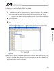
(2) The coordinate system definition data edit window will be displayed.
This window provides the following items:
A. Work Coordinate System
Offset No. Indicate the work coordinate system No.
X [0.001 mm] Enter the offset data for the X-axis.
Y [0.001 mm] Enter the offset data for the Y-axis.
Z [0.001 mm] Enter the offset data for the Z-axis.
R [0.001 deg] Enter the offset data for the R-axis.
B. Tool coordinate System
Offset No. Indicate the tool coordinate system No.
X [0.001 mm] Enter the offset data for the X-axis.
Y [0.001 mm] Enter the offset data for the Y-axis.
Z [0.001 mm] Enter the offset data for the Z-axis.
R [0.001 deg] Enter the offset data for the R-axis.
C. Simple Interference Check Zone
Zone No. Indicate the zone No.
Coordinates No. Indicate the coordinate No.
Coordinates 1 and Coordinates 2 are available.
X [0.001 mm] Enter the interference range data for the X-axis.
Y [0.001 mm] Enter the interference range data for the Y-axis.
Z [0.001 mm] Enter the interference range data for the Z-axis.
R [0.001 deg] Enter the interference range data for the R-axis.
Physical output port No.
Global flag No. Select the output number inside the check zone.
Error type Select the error type.
0 = Error handling is not performed.
1 = Message level error is output.
2 = Movement release level error is output.