
Instruction Manual

Chapter 6 Adjustment of Operation 6.3 I/O Parameter
6.3.1 Positioner Mode 1, Positioner Mode 2 and Pulse Train Control Mode
323
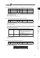
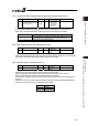
(35) PIO inch distance, PIO inch distance 2 (Parameter No.48, No.49)
No. Name Symbol Unit Input Range Default factory setting
48 PIO inch distance IOID mm 0.01 to 1.00 0.1
49
(Note1)
PIO inch distance 2 IOD2 mm 0.01 to 1.00 0.1
Set the inching distance for the inching input command from PLC when PIO Pattern = 1
(Teaching Mode) is selected in Positioner Mode 2.
The maximum allowable value is 1 mm.
Note 1 Parameter No.49 “PIO inch distance 2” is not used.
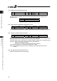
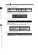
(36) Load output judgment time period (Parameter No.50)
No. Name Symbol Unit Input Range Default factory setting
50
Load output judgment time
period
LDWT msec 0 to 9999 255
This parameter is not used.
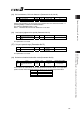
(37) Torque inspected range (Parameter No.51)
No. Name Symbol Unit Input Range Default factory setting
51 Torque inspected range TRQZ –
0 : Enabled
1 : Disabled
0
This parameter is not used.
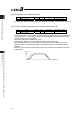
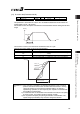
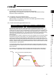
(38) Default acceleration/deceleration mode (Parameter No.52)
No. Name Symbol Unit Input Range Default factory setting
52
Default
acceleration/deceleration
mode
CTLF – 0 to 2 0 (Trapezoid)
These values are automatically set to “Acceleration/Deceleration Mode” of the applicable
position number when the target position is written to the unregistered position table.
Set Value Description
0 Trapezoid
1 S-motion
2 Primary delay filter