
Instruction Manual


Chapter 6 Adjustment of Operation 6.3 I/O Parameter
6.3.1 Positioner Mode 1, Positioner Mode 2 and Pulse Train Control Mode
307
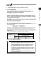
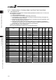
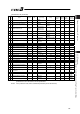
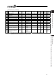
I/O Parameter List (Continued)
No.
Category
Name Symbol Unit Input Range
Default factory
setting
For
Positioner
Mode 1
For
Positioner
Mode 2
For Pulse
Train
Mode
Relevant
sections
This section
143 – Overload level ratio OLWL % 50 to 100 100 [2] (62)
144 B
Gain scheduling upper limit
multiplying ratio
GSUL % 0 to 1023 0
{ { {
[2] (63)
145 C GS velocity loop proportional gain GSPC – 1 to 30000 750
{ { {
[2] (64),
[3]
146 C GS velocity loop integral gain GSIC – 1 to 500000 4500
{ { {
[2] (65),
[3]
147 B Total movement count threshold TMCT times 0 to 999999999 0 (Disabled)
{ { {
[2] (66)
148 B Total operated distance threshold ODOT m 0 to 999999999 0 (Disabled)
{ { {
[2] (67)
149 B Zone output changeover FPIO –
0: To change
1: Not to change
0
{ {
[2] (68)
152 B High output setting BUEN –
0: Disabled
1: Enabled
1
{ { {
[2] (69)
153 B BU velocity loop proportional gain BUPC – 1 to 10000 200
{ { {
[2] (70),
[3]
154 B BU velocity loop integral gain BUIC – 1 to 100000 4000
{ { {
[2] (71),
[3]
155 A Absolute battery retention time AIP days
0: 20 days
1: 15 days
2: 10 days
3: 5 days
2
{
[2] (72)
156 B
Torque check/Light malfunction
output select
SLAL -
0: Torque check
effective
1: Light malfunction
effective
0
{
[2] (73)
(Note 1) The setting values vary in accordance with the specification of the actuator. At shipment, the
parameters are set in accordance with the specification.