
Instruction Manual

Chapter 3 Wiring 3.7 Wiring Method
145
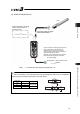
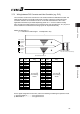
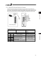
3.7.3 Wiring between PIO Converter and Host Controller (e.g. PLC)
The connection of I/O for PIO Converter is to be conducted with the dedicated I/O cable. The
cable length is shown in the model code of PIO Converter. Check the model code of PIO
Converter. Selection can be made from 3m or 5m as well as standard 2m. 10m is also
applicable at maximum if purchased separately. [Refer to 1.1.5 How to read the model]
Also, the end of the cable harness to be connected to the host controller (PLC, etc.) is just cut
and no treatment is conducted so the wiring layout can be performed freely.
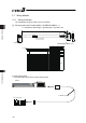
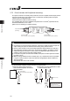
Model: CB-PAC-PIOƑƑƑ
(ƑƑƑ indicates the cable length L. Example 020 = 2m)
Flat Cable (20-core)
×
2
BK-4 (20B)
BR-3 (1B)
BK-2 (20A)
BR-1 (1A)
20A 20B
1A 1B
Half Pitch MIL Socket
HIF6-40D-1.27R (Hirose Electric)
A
B
L
No treatment
conducted
No treatment
conducted
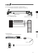
No.
Cable
Color
Wiring No.
Cable
Color
Wiring
1A BR-1 1B BR-3
2A RD-1 2B RD-3
3A OR-1 3B OR-3
4A YW-1 4B YW-3
5A GN-1 5B GN-3
6A BL-1 6B BL-3
7A PL-1 7B PL-3
8A GY-1 8B GY-3
9A WT-1 9B WT-3
10A BK-1 10B BK-3
11A BR-2 11B BR-4
12A RD-2 12B RD-4
13A OR-2 13B OR-4
14A YW-2 14B YW-4
15A GN-2 15B GN-4
16A BL-2 16B BL-4
17A PL-2 17B PL-4
18A GY-2 18B GY-4
19A WT-2 19B WT-4
20A BK-2
Flat Cable
٤
A
(Press Welding)
AWG28
20B BK-4
Flat Cable
٤
B
(Press Welding)
AWG28
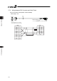
For the signal assignment of each wire, refer to the following considering the operation mode.
1) Positioner Mode 2 ·············3.3.3 [3] PIO Circuit
2) MEC Mode 2 ·····················3.5.3 [3] PIO Circuit