
Instruction Manual

Chapter 3 Wiring3.4 MEC Mode 1 (Operation with PLC)
128
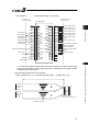
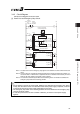
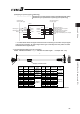
[2] PIO Circuit
1) Stopping at 2 points (2-point positioning)
·······································Movement by 1 input between 2 points (Single-solenoid mode)
0V (NPN Type)
24V DC (PNP Type)
Move Signal 1
Reset
Pause
ERC3
A9
B9
A10
B10
A11
B11
A12
B12
A13
B13
ST0
RES
LS0/PE0
LS1/PE1
HEND
*ALM
24V DC (NPN Type)
0V (PNP Type)
Start point detection/
Positioning to start point complete
End point detection/
Positioning to end point complete
Home Return Completion
Alarm
BR 2
RD 2
OR 2
YW 2
GN 2
BL 2
PL 2
GY 2
WT 2
BK
“*” in codes above shows the signal of the active low. Processing occurs when an input signal
of the type is turned OFF. An output signal of the type is normally ON in the power-on status
and turned OFF at signal output.
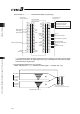
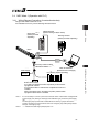
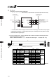
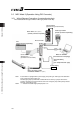
Ɣ For the connection of I/O, use the enclosed cable for those connections including the power
supply and emergency stop circuit.
Model : CB-ERC3P-PWBIOƑƑƑ (ƑƑƑ indicates the cable length L. Example. 020 2m)
L
B A
10
13
12
11
2
3
9
8
7
6
5
4
1
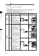
Display of Mode Code
Pin No.
Wire
Color
Signal
Abbreviation
Width Pin No.
Wire
Color
Signal
Abbreviation
Width
A1 Drain FG
AWG22
(0.3mm
2
)
B1 BR CP
A2 – – – B2 RD CP_GND
AWG22
(0.3mm
2
)
A3 RD 1 BK B3 OR MP
A4 OR 1 EMG
AWG28
(0.08mm
2
)
B4 YW MP_GND
AWG19
(0.75mm
2
)
A5 – – – B5 GN –
A6 – – – B6 BR 1 –
A7 BL – B7 PL –
A8 GY – B8 WT –
A9 BR 2 ST01 B9 RD 2 –
A10 OR 2 RES B10 YW 2 –
A11 GN 2 – B11 BL 2 –
A12 PL 2 LS0/PE0 B12 GY 2 LS1/PE1
A13 WT 2 HEND
AWG28
(0.08mm
2
)
B13 BK *ALM
AWG28
(0.08mm
2
)
(Note) Wire color No.1 is colored with short-dotted line and No.2 with long-dotted line.