
Instruction Manual
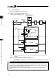

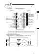
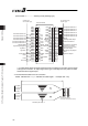
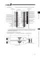

Chapter 3 Wiring 3.3 Positioner Mode 2 (Extension Type by PIO Converter)
111
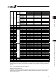
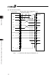
Parameter No.25 (PIO Pattern) Selection
3 4 5
Category
PIO Functions
512-point mode Solenoid valve mode 1 Solenoid valve mode 2
Number of
positioning points
512 points 7 points 3 points
Home return
signal
{ { u
Jog signal u u u
Teaching signal
(Current position
writing)
u u u
Input
Brake release { { {
Moving signal u u u
Zone signal u { {
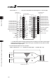
Pin No.
Wire
Color
Output
Position zone
signal
u { {
1A BR-1 – –
2A RD-1 – –
3A OR-1 – –
4A YW-1 – –
5A GN-1 IN0 PC1 ST0 ST0
6A BL-1 IN1 PC2 ST1 ST1(JOG+)
7A PL-1 IN2 PC4 ST2 ST2
(Note 1)
8A GY-1 IN3 PC8 ST3 –
9A WT-1 IN4 PC16 ST4 –
10A BK-1 IN5 PC32 ST5 –
11A BR-2 IN6 PC64 ST6 –
12A RD-2 IN7 P128 – –
13A OR-2 IN8 PC256 – –
14A YW-2 IN9 BKRL BKRL BKRL
15A GN-2 IN10 – – –
16A BL-2 IN11 HOME HOME –
17A PL-2 IN12 *STP *STP –
18A GY-2 IN13 CSTR – –
19A WT-2 IN14 RES RES RES
20A BK-2
Input
IN15 SON SON SON
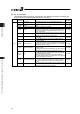
1B BR-3 OUT0 PM1(ALM1) PE0 LSO
2B RD-3 OUT1 PM2(ALM2) PE1 LS1(TRQS)
3B OR-3 OUT2 PM4(ALM4) PE2 LS2
(Note 1)
4B YW-3 OUT3 PM8(ALM8) PE3 –
5B GN-3 OUT4 PM16 PE4 –
6B BL-3 OUT5 PM32 PE5 –
7B PL-3 OUT6 PM64 PE6 –
8B GY-3 OUT7 PM128 ZONE1 ZONE1
9B WT-3 OUT8 PM256 PZONE/ZONE2 PZONE/ZONE2
10B BK-3 OUT9 – – –
11B BR-4 OUT10 HEND HEND HEND
12B RD-4 OUT11 PEND PEND –
13B OR-4 OUT12 SV SV SV
14B YW-4 OUT13 *EMGS *EMGS *EMGS
15B GN-4 OUT14 *ALM *ALM *ALM
16B BL-4
Output
OUT15 *ALML *ALML *ALML
17B PL-4 – –
18B GY-4 – –
19B WT-4 – –
20B BK-4 – –
Signal with “*” expresses the signal of active low.
PM1 to PM8 are the binary code output signals of an alarm while it is being generated. [Refer to 4.2.3 [5]]
PZONE (position zone signal) can be switched over to ZONE (zone signal) with the setting of Parameter
No.149.
Note 1 It is invalid before home-return operation.
(Reference) Signal of Active Low
Signal with “*” expresses the signal of active low. A signal of active low is a signal that the input signal is
processed when it is turned OFF, output signal is ordinary ON while the power is ON, and turns OFF
when the signal is output.