
Instruction Manual
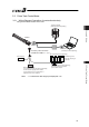

Chapter 3 Wiring3.3 Positioner Mode 2 (Extension Type by PIO Converter)
110
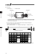
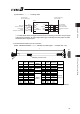
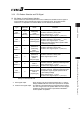
[2] PIO Patterns and Signal Assignment
The signal assignment of cable by the PIO pattern is as shown below. Follow the following
table to connect the external equipment (such as PLC).
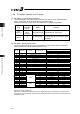
Parameter No.25 (PIO Pattern) Selection
0 1 2
Category
PIO Functions
Positioning mode Teaching mode 256-point mode
Number of positioning
points
64 points 64 points 256 points
Home return signal { { {
Jog signal u { u
Teaching signal
(Current position writing)
u { u
Input
Brake release { u {
Moving signal { { u
Zone signal { u u
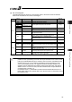
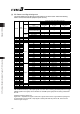
Pin No.
Wire
Color
Output
Position zone signal { { {
1A BR-1 – –
2A RD-1 – –
3A OR-1 – –
4A YW-1 – –
5A GN-1 IN0 PC1 PC1 PC1
6A BL-1 IN1 PC2 PC2 PC2
7A PL-1 IN2 PC4 PC4 PC4
8A GY-1 IN3 PC8 PC8 PC8
9A WT-1 IN4 PC16 PC16 PC16
10A BK-1 IN5 PC32 PC32 PC32
11A BR-2 IN6 – MODE PC64
12A RD-2 IN7 – JISL PC128
13A OR-2 IN8 – JOG+ –
14A YW-2 IN9 BKRL JOG- BKRL
15A GN-2 IN10 – – –
16A BL-2 IN11 HOME HOME HOME
17A PL-2 IN12 *STP *STP *STP
18A GY-2 IN13 CSTR CSTR/PWRT CSTR
19A WT-2 IN14 RES RES RES
20A BK-2
Input
IN15 SON SON SON
1B BR-3 OUT0 PM1(ALM1) PM1(ALM1) PM1(ALM1)
2B RD-3 OUT1 PM2(ALM2) PM2(ALM2) PM2(ALM2)
3B OR-3 OUT2 PM4(ALM4) PM4(ALM4) PM4(ALM4)
4B YW-3 OUT3 PM8(ALM8) PM8(ALM8) PM8(ALM8)
5B GN-3 OUT4 PM16 PM16 PM16
6B BL-3 OUT5 PM32 PM32 PM32
7B PL-3 OUT6 MOVE MOVE PM64
8B GY-3 OUT7 ZONE1 MODES PM128
9B WT-3 OUT8 PZONE/ZONE2 PZONE/ZONE1 PZONE/ZONE1
10B BK-3 OUT9 – – –
11B BR-4 OUT10 HEND HEND HEND
12B RD-4 OUT11 PEND PEND/WEND PEND
13B OR-4 OUT12 SV SV SV
14B YW-4 OUT13 *EMGS *EMGS *EMGS
15B GN-4 OUT14 *ALM *ALM *ALM
16B BL-4
Output
OUT15 *ALML *ALML *ALML
17B PL-4 – –
18B GY-4 – –
19B WT-4 – –
20B BK-4 – –
Signal with “*” expresses the signal of active low.
PM1 to PM8 are the binary code output signals of an alarm while it is being generated. [Refer to 4.2.3 [5]]
PZONE (position zone signal) can be switched over to ZONE (zone signal) with the setting of Parameter
No.149.
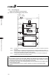
(Reference) Signal of Active Low
Signal with “*” expresses the signal of active low. A signal of active low is a signal that the input signal is
processed when it is turned OFF, output signal is ordinary ON while the power is ON, and turns OFF
when the signal is output.