
Instruction Manual

Chapter 3 Wiring3.2 Pulse Train Control Mode
106
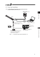
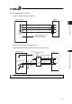
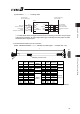
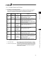
[3] PIO Circuit
(1) PIO Pattern 0 ·················Positioning mode
0V (NPN Type)
24V DC (PNP Type)
Servo ON
Home Return
Torque Limit Select
Reset
ERC3
A9
B9
A10
B10
A12
B12
A13
B13
SON
TL
HOME
RES
SV
INP
HEND
*ALM
24V DC (NPN Type)
0V (PNP Type)
Servo ON Status
Position Complete
Home Return Completion
Alarm
BR 2
RD 2
OR 2
YW 2
PL 2
GY 2
WT 2
BK
“*” in codes above shows the signal of the active low. Processing occurs when an input signal
of the type is turned OFF. An output signal of the type is normally ON in the power-on status
and turned OFF at signal output.
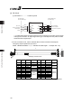
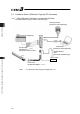
Ɣ For the connection of I/O, use the enclosed cable for those connections including the
emergency stop and pulse train input circuit.
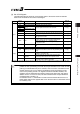
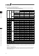
Model : CB-ERC3P-PWBIOƑƑƑ (ƑƑƑ indicates the cable length L. Example. 020 2m)
L
B A
10
13
12
11
2
3
9
8
7
6
5
4
1
Display of Mode Code
Pin No.
Wire
Color
Signal
Abbreviation
Width Pin No.
Wire
Color
Signal
Abbreviation
Width
A1 Drain FG
AWG22
(0.3mm
2
)
B1 BR CP
A2 – – – B2 RD CP_GND
AWG22
(0.3mm
2
)
A3 RD 1 BK B3 OR MP
A4 OR 1 EMG
AWG28
(0.08mm
2
)
B4 YW MP_GND
AWG19
(0.75mm
2
)
A5 – – – B5 GN –
A6 – – – B6 BR 1 –
A7 BL – B7 PL –
A8 GY – B8 WT –
A9 BR 2 SON1 B9 RD 2 TL
A10 OR 2 HOME B10 YW 2 RES
A11 GN 2 – B11 BL 2 –
A12 PL 2 SV B12 GY 2 INP
A13 WT 2 HEND
AWG28
(0.08mm
2
)
B13 BK *ALM
AWG28
(0.08mm
2
)
(Note) Wire color No.1 is colored with short-dotted line and No.2 with long-dotted line.