
Instruction Manual

Chapter 3 Wiring3.2 Pulse Train Control Mode
102
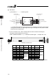
3.2.2 PIO Pattern Selection and PIO Signal
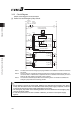
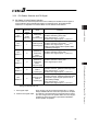
[1] PIO Pattern (Control Pattern) Selection
There are two types of control method for the pulse train control. Set an appropriate PIO
pattern suited to the use to Parameter No.25 “PIO Pattern Select”.
Refer to 4.3 Operation in Pulse Train Control Mode for the details of PIO patterns.
Type
Value set in
parameter
No.25
Mode Overview
PIO
Pattern 0
0
(at the
delivery)
Positioning mode • Positioning with Pulse Train
PIO
Pattern 1
1 Pressing mode
• Positioning with Pulse Train
• Pressing operation with torque control
available
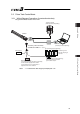
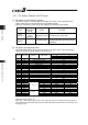
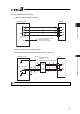
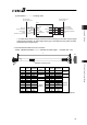
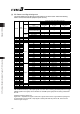
[2] PIO pattern and Signal Allocation
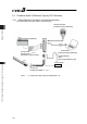
The signal assignment of cable by the PIO pattern is as shown below. Follow the following
table to connect the external equipment (such as PLC).
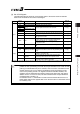
Parameter No.25 (PIO Pattern) Selection
0 1
Pin No. Wire Color Category PIO Function
Positioning mode Pressing mode
A1 Drain
Frame ground FG
B1 BR
Control power unit +24V CP
A2 –
– –
B2 RD
Control power unit 0V CP_GND
A3 RD 1 Brake release
BK
B3 OR Motor power unit +24V
MP
A4 OR 1 Emergency-stop input
EMG
B4 YW Motor power unit 0V
MP_GND
A5 –
– –
B5 GN
– –
A6 –
– –
B6 BR 1
– –
A7 BL
– /PP
B7 PL
– PP
A8 GY
– /NP
B8 WT
– NP
A9 BR 2
IN0 SON SON
B9 RD 2
IN1 TL TL
A10 OR 2
IN2 HOME HOME
B10 YW 2
IN3 RES RES/DCLR
A11 GN 2
IN4 – –
B11 BL 2
Input
IN5 – –
A12 PL 2
OUT0 SV SV
B12 GY 2
OUT1 INP INP/TLR
A13 WT 2
OUT2 HEND HEND
B13 BK
Output
OUT3 *ALM *ALM
Signal with “*” expresses the signal of active low.
(Reference) Signal of Active Low
Signal with “*” expresses the signal of active low. A signal of active low is a signal that the input signal is
processed when it is turned OFF, output signal is ordinary ON while the power is ON, and turns OFF when
the signal is output.