
Instruction Manual
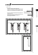
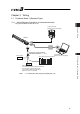


Chapter 3 Wiring 3.1 Positioner Mode 1 (Standard Type)
95
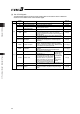
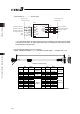
[2] PIO Patterns and Signal Assignment
The signal assignment of cable by the PIO pattern is as shown below. Follow the following table
to connect the external equipment (such as PLC).
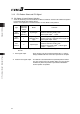
Parameter No.25 (PIO Pattern) Selection
0 1 2
Category
PIO Functions
8-point type
3-point (solenoid
valve) type
16-point type
Number of positioning
points
8 points 3 points 16 points
Home return signal {
u u
Jog signal
u u u
Teaching signal
(Current position writing)
u u u
Input
Brake release { { {
Moving signal
u u u
Zone signal {
u
{
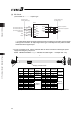
Pin No. Wire Color
Output
Position zone signal
u u u
A1 Drain Frame ground
FG
B1 BR Control power unit +24V
CP
A2 –
– –
B2 RD
Control power unit 0V CP_GND
A3 RD 1
Brake release BK
B3 OR Motor power unit +24V
MP
A4 OR 1 Emergency-stop input
EMG
B4 YW Motor power unit 0V
MP_GND
A5 –
– –
B5 GN
– –
A6 –
– –
B6 BR 1
– –
A7 BL
– –
B7 PL
– –
A8 GY
– –
B8 WT
– –
A9 BR 2
IN0 PC1 ST0 PC1
B9 RD 2
IN1 PC2 ST1 PC2
A10 OR 2
IN2 PC4 ST2 PC4
B10 YW 2
IN3 HOME – PC8
A11 GN 2
IN4 CSTR RES CSTR
B11 BL 2
Input
IN5 *STP *STP *STP
A12 PL 2
OUT0 PEND PE0 PEND
B12 GY 2
OUT1 HEND PE1 HEND
A13 WT 2
OUT2 ZONE1 PE2
PZONE/
ZONE1
B13 BK
Output
OUT3 *ALM *ALM *ALM
(Note) Signal with “*” expresses the signal of active low.
(Reference) Signal of Active Low
Signal with “*” expresses the signal of active low. A signal of active low is a signal that the input signal is
processed when it is turned OFF, output signal is ordinary ON while the power is ON, and turns OFF when
the signal is output.