
Owner's manual


Table Of Contents
- Cover
- Please Read Before Use
- CAUTION
- CE Marking
- Table of Contents
- Safety Guide
- Caution in Handling
- 1. Overview
- 2. Installation
- 3. Wiring
- 3.1 Basic Structure
- 3.2 Configuration Using a SIO Converter
- 3.3 Configuration Using an Isolated PIO Terminal Block
- 3.4 Configuration Using Both SIO Converter and Isolated PIO Terminal Block
- 3.5 Specifications of I/O Signals
- 3.6 I/O Signals for PIO Pattern 1 [3 Points] (Air Cylinder)
- 3.7 I/O Signals for PIO Pattern 0 [8 Points]
- 3.8 I/O Signals for PIO Pattern 2 [16 Points] (Setting by Zone BoundaryParameters)
- 3.9 I/O Signals for PIO Pattern 3 [16 Points] (Setting in Zone Fields in thePosition Table)
- 3.10 Emergency-Stop Circuit
- 3.11 Extension Cable
- 4. Electrical Specifications
- 5. Data Entry
- 6. Operation in the “3 Points (Air Cylinder)” Mode
- 7. Operation in the “8 Points” and “16 Points” Modes
- 7.1 How to Start
- 7.2 Position Table and Parameter Settings Required for Operation
- 7.3 How to Execute Home Return
- 7.4 Home Return and Movement after Start (16 Points)
- 7.5 Positioning Mode (Back and Forth Movement between Two Points)
- 7.6 Push & Hold Mode
- 7.7 Speed Change during Movement
- 7.8 Operation at Different Acceleration and Deceleration Settings
- 7.9 Pause
- 7.10 Zone Signal
- 7.11 Incremental Moves
- 7.12 Notes on Incremental Mode
- 8. Parameter Settings
- 9. Troubleshooting
- 10. Maintenance and Inspection
- 11. Appendix
- Change History
84
5. Data Entry <Basic>
75
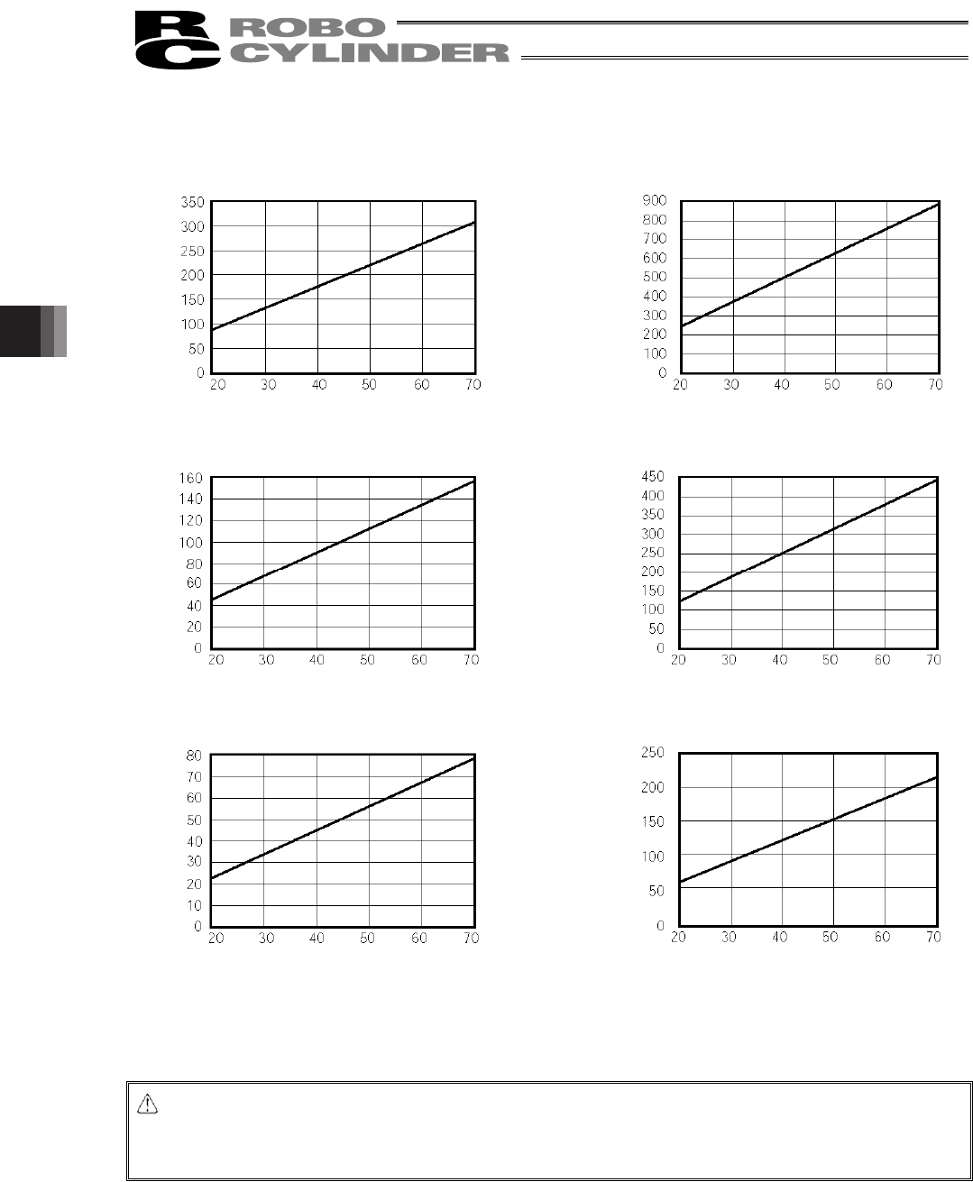
z Rod type
(1) RA6C type (2) RA7C type
Low-speed type Low-speed type
(Lead: 3 mm) (Lead: 4 mm)
Medium-speed type Me
dium-speed type
(Lead: 6 mm) (Lead: 8 mm)
High-speed type Hi
gh-speed type
(Lead: 12 mm) (Lead: 16 mm)
Caution: The accuracy of push force at standstill is not guaranteed. The above graphs are provided for
reference purposes only. If the push force is too small, malfunction may occur during push & hold
operation due to slide resistance, etc., so exercise caution.
The maximum current-limiting value is shown in the above graphs. The minimum value is 20%.
Push force (N)
Push force (N)
Current-limiting value (%) Current-limiting value (%)
Push force (N)
Push force (N)
Push force (N)
Push force (N)
Current-limiting value (%) Current-limiting value (%)
Current-limiting value (%) Current-limiting value (%)