
Owner's manual


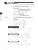


Table Of Contents
- Cover
- Please Read Before Use
- CAUTION
- CE Marking
- Table of Contents
- Safety Guide
- Caution in Handling
- 1. Overview
- 2. Installation
- 3. Wiring
- 3.1 Basic Structure
- 3.2 Configuration Using a SIO Converter
- 3.3 Configuration Using an Isolated PIO Terminal Block
- 3.4 Configuration Using Both SIO Converter and Isolated PIO Terminal Block
- 3.5 Specifications of I/O Signals
- 3.6 I/O Signals for PIO Pattern 1 [3 Points] (Air Cylinder)
- 3.7 I/O Signals for PIO Pattern 0 [8 Points]
- 3.8 I/O Signals for PIO Pattern 2 [16 Points] (Setting by Zone BoundaryParameters)
- 3.9 I/O Signals for PIO Pattern 3 [16 Points] (Setting in Zone Fields in thePosition Table)
- 3.10 Emergency-Stop Circuit
- 3.11 Extension Cable
- 4. Electrical Specifications
- 5. Data Entry
- 6. Operation in the “3 Points (Air Cylinder)” Mode
- 7. Operation in the “8 Points” and “16 Points” Modes
- 7.1 How to Start
- 7.2 Position Table and Parameter Settings Required for Operation
- 7.3 How to Execute Home Return
- 7.4 Home Return and Movement after Start (16 Points)
- 7.5 Positioning Mode (Back and Forth Movement between Two Points)
- 7.6 Push & Hold Mode
- 7.7 Speed Change during Movement
- 7.8 Operation at Different Acceleration and Deceleration Settings
- 7.9 Pause
- 7.10 Zone Signal
- 7.11 Incremental Moves
- 7.12 Notes on Incremental Mode
- 8. Parameter Settings
- 9. Troubleshooting
- 10. Maintenance and Inspection
- 11. Appendix
- Change History

81
5. Data Entry <Basic>
72
(9) Acceleration/deceleration
mode
x This field is not used for this controller.
The factory setting is “0.”
(10) Incremental
x This setting defines whether to use the absolute mode or incremental mode.
The factory setting is “0.”
0: Absolute mode
1: Incremental mode
(11) Command mode
x This field is not used for this controller.
The factory setting is “0.”
(12) Standstill mode
x This setting defines the power-saving mode to be applied when the actuator is
standing by after completing the positioning to the target position set in the
“Position” field for the applicable position number.
0: All power-saving modes are disabled. * The factory setting is “0: [Disable].”
1: Automatic servo-off mode. The delay time is defined by parameter No. 36.
2: Automatic servo-off mode. The delay time is defined by parameter No. 37.
3: Automatic servo-off mode. The delay time is defined by parameter No. 38.
4: Full servo control mode
Full servo control mode
The pulse motor is servo-controlled to reduce the holding current.
Although the exact degree of current reduction varies depending on the actuator model, load condition, etc., the
holding current decreases to approx. one-half to one-fourth.
Since the servo remains on, no position deviation occurs.
The actual holding current can be checked in the current monitor screen of the PC software.
Automatic servo-off mode
After positioning is completed, the servo will turn off upon elapse of a specified time.
(Since no holding current flows, the power consumption decreases.)
When the PLC issues the next movement command, the servo will turn on and the actuator will start moving.
Movement
command
Servo status
A
ctuator
movement
Servo on
Automatic servo-off mode
(the green LED blinks)
Target position
T: Delay time after the positioning is
completed until the servo turns off (sec).
Set by a parameter.