
Owner's manual


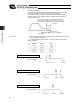


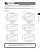


Table Of Contents
- Cover
- Please Read Before Use
- CAUTION
- CE Marking
- Table of Contents
- Safety Guide
- Caution in Handling
- 1. Overview
- 2. Installation
- 3. Wiring
- 3.1 Basic Structure
- 3.2 Configuration Using a SIO Converter
- 3.3 Configuration Using an Isolated PIO Terminal Block
- 3.4 Configuration Using Both SIO Converter and Isolated PIO Terminal Block
- 3.5 Specifications of I/O Signals
- 3.6 I/O Signals for PIO Pattern 1 [3 Points] (Air Cylinder)
- 3.7 I/O Signals for PIO Pattern 0 [8 Points]
- 3.8 I/O Signals for PIO Pattern 2 [16 Points] (Setting by Zone BoundaryParameters)
- 3.9 I/O Signals for PIO Pattern 3 [16 Points] (Setting in Zone Fields in thePosition Table)
- 3.10 Emergency-Stop Circuit
- 3.11 Extension Cable
- 4. Electrical Specifications
- 5. Data Entry
- 6. Operation in the “3 Points (Air Cylinder)” Mode
- 7. Operation in the “8 Points” and “16 Points” Modes
- 7.1 How to Start
- 7.2 Position Table and Parameter Settings Required for Operation
- 7.3 How to Execute Home Return
- 7.4 Home Return and Movement after Start (16 Points)
- 7.5 Positioning Mode (Back and Forth Movement between Two Points)
- 7.6 Push & Hold Mode
- 7.7 Speed Change during Movement
- 7.8 Operation at Different Acceleration and Deceleration Settings
- 7.9 Pause
- 7.10 Zone Signal
- 7.11 Incremental Moves
- 7.12 Notes on Incremental Mode
- 8. Parameter Settings
- 9. Troubleshooting
- 10. Maintenance and Inspection
- 11. Appendix
- Change History

79
5. Data Entry <Basic>
70
(4) Acceleration/Deceleration
x Enter the acceleration/deceleration at which the actuator will be moved, in [G].
Basically, you should set values within the rated range specified in the
catalog.
The input range is greater than the rated range in the catalog, in order to
accommodate situations where you want to “shorten the tact time when the
transferring mass is much smaller than the rated loading capacity.”
If the load vibrates during acceleration/deceleration and causes problem,
decrease the set values.
Increasing the set value makes acceleration/deceleration quicker, while
decreasing the set value makes acceleration/deceleration more gradual.
Caution: When setting the speed and acceleration/deceleration, refer to 1.3, “Specifications” and enter
appropriate values that will prevent the actuator from receiving excessive impact or vibration, by
considering the installation conditions and shape of the load. Increasing the speed and
acceleration/deceleration changes the ltransferring mass significantly, and the actuator
characteristics also vary from one model to another. Therefore, consult IAI’s Sales Engineering
Section for the maximum limits that can be entered in your specific application.
(5) Push
x Select “positioning operation” or “push & hold operation.”
The factory setting is “0.”
0: Normal positioning operation
Other than 0: Push & hold operation (The set value defines the current-
limiting value.)
(6) Threshold
x This field is not used for this controller.
The factory setting is “0.”
(7) Positioning band
x The meaning of the positioning band varies between “positioning operation”
and “push & hold operation.”
“Positioning operation”
The set value defines the distance
before the target position at which the
position complete signal will turn ON.
Increasing the positioning band
quickens the start of the next operation
in the sequence, meaning that the tact
time can be reduced. Set an
appropriate value based on the overall
balance of your system.
Speed
A
cceleration Deceleration
Time
Starting
position
Target
position
The position complete
signal turns ON here.
Positioning band
Target
position