
Owner's manual


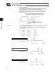


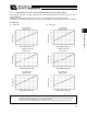


Table Of Contents
- Cover
- Please Read Before Use
- CAUTION
- CE Marking
- Table of Contents
- Safety Guide
- Caution in Handling
- 1. Overview
- 2. Installation
- 3. Wiring
- 3.1 Basic Structure
- 3.2 Configuration Using a SIO Converter
- 3.3 Configuration Using an Isolated PIO Terminal Block
- 3.4 Configuration Using Both SIO Converter and Isolated PIO Terminal Block
- 3.5 Specifications of I/O Signals
- 3.6 I/O Signals for PIO Pattern 1 [3 Points] (Air Cylinder)
- 3.7 I/O Signals for PIO Pattern 0 [8 Points]
- 3.8 I/O Signals for PIO Pattern 2 [16 Points] (Setting by Zone BoundaryParameters)
- 3.9 I/O Signals for PIO Pattern 3 [16 Points] (Setting in Zone Fields in thePosition Table)
- 3.10 Emergency-Stop Circuit
- 3.11 Extension Cable
- 4. Electrical Specifications
- 5. Data Entry
- 6. Operation in the “3 Points (Air Cylinder)” Mode
- 7. Operation in the “8 Points” and “16 Points” Modes
- 7.1 How to Start
- 7.2 Position Table and Parameter Settings Required for Operation
- 7.3 How to Execute Home Return
- 7.4 Home Return and Movement after Start (16 Points)
- 7.5 Positioning Mode (Back and Forth Movement between Two Points)
- 7.6 Push & Hold Mode
- 7.7 Speed Change during Movement
- 7.8 Operation at Different Acceleration and Deceleration Settings
- 7.9 Pause
- 7.10 Zone Signal
- 7.11 Incremental Moves
- 7.12 Notes on Incremental Mode
- 8. Parameter Settings
- 9. Troubleshooting
- 10. Maintenance and Inspection
- 11. Appendix
- Change History

78
5. Data Entry <Basic>
69
5. Data Entry <Basic>
To move the actuator to a specified position, you must enter the target position in the “Position” field of the position
table.
The target position can be specified in two different modes: by absolute coordinate specification (absolute mode) in
which the distance from the home is entered, or by relative coordinate specification (incremental mode) in which the
incremental travel from the current position is entered.
Once the target position is entered, other fields will be automatically populated by the default values set by the
parameters.
The default values vary in accordance with the characteristics of the actuator.
5.1 Description of Position Table
The position table is explained by using the screen on the PC software as an example.
(The displayed items vary on the teaching pendant screen.)
(1) No.
x Indicate the position data number. A position is defined as explained below.
(2) Position
x Enter the target position to move the actuator to, in [mm].
Absolute mode: Enter the distance to the target actuator position from
the actuator’s home.
Incremental mode: Enter the distance to the target actuator position from
the current position by assuming a movement by
constant pitch feed.
(3) Speed
x Enter the speed at which the actuator will be moved, in [mm/sec].
The default value varies depending on the actuator type.
Position Speed Acceleration Deceleration Push Threshold
Positioning
band
Zone+ Zone–
Acceleration/
deceleration
mode
Incremental
Command
mode
Standstill
mode
Comment
Standby position
A
bsolute mode The target is 30 mm from the home.
Incremental mode +10 mm from the current position.
Incremental mode -10 mm from the current position.
Position
* On the teaching pendant screen, this sign indicates
that the position is specified in the incremental mode.