
Owner's manual


Table Of Contents
- Cover
- Please Read Before Use
- CAUTION
- CE Marking
- Table of Contents
- Safety Guide
- Caution in Handling
- 1. Overview
- 2. Installation
- 3. Wiring
- 3.1 Basic Structure
- 3.2 Configuration Using a SIO Converter
- 3.3 Configuration Using an Isolated PIO Terminal Block
- 3.4 Configuration Using Both SIO Converter and Isolated PIO Terminal Block
- 3.5 Specifications of I/O Signals
- 3.6 I/O Signals for PIO Pattern 1 [3 Points] (Air Cylinder)
- 3.7 I/O Signals for PIO Pattern 0 [8 Points]
- 3.8 I/O Signals for PIO Pattern 2 [16 Points] (Setting by Zone BoundaryParameters)
- 3.9 I/O Signals for PIO Pattern 3 [16 Points] (Setting in Zone Fields in thePosition Table)
- 3.10 Emergency-Stop Circuit
- 3.11 Extension Cable
- 4. Electrical Specifications
- 5. Data Entry
- 6. Operation in the “3 Points (Air Cylinder)” Mode
- 7. Operation in the “8 Points” and “16 Points” Modes
- 7.1 How to Start
- 7.2 Position Table and Parameter Settings Required for Operation
- 7.3 How to Execute Home Return
- 7.4 Home Return and Movement after Start (16 Points)
- 7.5 Positioning Mode (Back and Forth Movement between Two Points)
- 7.6 Push & Hold Mode
- 7.7 Speed Change during Movement
- 7.8 Operation at Different Acceleration and Deceleration Settings
- 7.9 Pause
- 7.10 Zone Signal
- 7.11 Incremental Moves
- 7.12 Notes on Incremental Mode
- 8. Parameter Settings
- 9. Troubleshooting
- 10. Maintenance and Inspection
- 11. Appendix
- Change History
74
4. Electrical Specifications
65
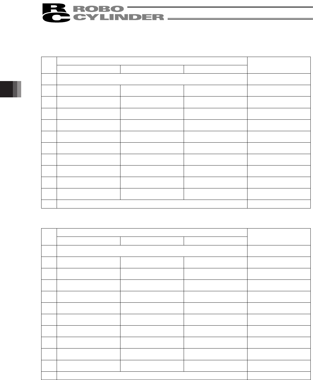
[6] PIO connection terminal block (TB3)
A PLC connection port. Detailed signal specifications are shown below.
[1] RCB-TU-PIO-A/B (When the control board is of the NPN specification)
PIO pattern
TB3
0 (8-point type) 1 (3-point
type) 2, 3 (16-point type)
Remarks
1 Input common (In-COM) 24 [V] (Note 1)
LED 11 illuminates when
24 V is supplied.
2 Command position 1 (PC1) Move to rear end (ST0) Command position 1 (PC1)
LED1 illuminates when this
signal turns ON.
3 Command position 2 (PC2) Move to front end (ST1) Command position 2 (PC2)
LED2 illuminates when this
signal turns ON.
4 Command position 4 (PC4)
Move to intermediate point
(ST2)
Command position 4 (PC4)
LED3 illuminates when this
signal turns ON.
5 Home return (HOME) Command position 8 (PC8)
LED4 illuminates when this
signal turns ON.
6 Start (CSTR) Start (CSTR)
LED5 illuminates when this
signal turns ON.
7 *Pause (*STP) *Pause (*STP) *Pause (*STP)
LED6 illuminates when this
signal turns ON.
8 Position complete (PEND) Rear end (PE0) Position complete (PEND)
LED7 illuminates when this
signal turns ON.
9
Home-return completion
(HEND)
Front end (PE1)
Home-return completion
(HEND)
LED8 illuminates when this
signal turns ON.
10 Zone output (ZONE) Intermediate point (PE2) Zone output (ZONE)
LED9 illuminates when this
signal turns ON.
11 *Alarm (*ALM) *Alarm (*ALM) *Alarm (*ALM)
LED10 illuminates when
this signal turns ON.
12 Output common (Out-COM) 0 [V] (Note 1)
(Note 1) The input common and output common become 0 [V] and 24 [V], respectively, in the PNP specification.
[2] RCB-TU-PIO-AP/BP (When the control board is of the PNP specification)
PIO pattern
TB3
0 (8-point type) 1 (3-point
type) 2, 3 (16-point type)
Remarks
1 Input common (In-COM) 0 [V] (Note 2)
LED 11 illuminates when
24 V is supplied.
2 Command position 1 (PC1) Move to rear end (ST0) Command position 1 (PC1)
LED1 illuminates when this
signal turns ON.
3 Command position 2 (PC2) Move to front end (ST1) Command position 2 (PC2)
LED2 illuminates when this
signal turns ON.
4 Command position 4 (PC4)
Move to intermediate point
(ST2)
Command position 4 (PC4)
LED3 illuminates when this
signal turns ON.
5 Home return (HOME) Command position 8 (PC8)
LED4 illuminates when this
signal turns ON.
6 Start (CSTR) Start (CSTR)
LED5 illuminates when this
signal turns ON.
7 *Pause (*STP) *Pause (*STP) *Pause (*STP)
LED6 illuminates when this
signal turns ON.
8 Position complete (PEND) Rear end (PE0) Position complete (PEND)
LED7 illuminates when this
signal turns ON.
9
Home-return completion
(HEND)
Front end (PE1)
Home-return completion
(HEND)
LED8 illuminates when this
signal turns ON.
10 Zone output (ZONE) Intermediate point (PE2) Zone output (ZONE)
LED9 illuminates when this
signal turns ON.
11 *Alarm (*ALM) *Alarm (*ALM) *Alarm (*ALM)
LED10 illuminates when
this signal turns ON.
12 Output common (Out-COM) 24 [V] (Note 2)
(Note 2) The input common and output common become 24 [V] and 0 [V], respectively, in the NPN specification.