
Owner's manual


Table Of Contents
- Cover
- Please Read Before Use
- CAUTION
- CE Marking
- Table of Contents
- Safety Guide
- Caution in Handling
- 1. Overview
- 2. Installation
- 3. Wiring
- 3.1 Basic Structure
- 3.2 Configuration Using a SIO Converter
- 3.3 Configuration Using an Isolated PIO Terminal Block
- 3.4 Configuration Using Both SIO Converter and Isolated PIO Terminal Block
- 3.5 Specifications of I/O Signals
- 3.6 I/O Signals for PIO Pattern 1 [3 Points] (Air Cylinder)
- 3.7 I/O Signals for PIO Pattern 0 [8 Points]
- 3.8 I/O Signals for PIO Pattern 2 [16 Points] (Setting by Zone BoundaryParameters)
- 3.9 I/O Signals for PIO Pattern 3 [16 Points] (Setting in Zone Fields in thePosition Table)
- 3.10 Emergency-Stop Circuit
- 3.11 Extension Cable
- 4. Electrical Specifications
- 5. Data Entry
- 6. Operation in the “3 Points (Air Cylinder)” Mode
- 7. Operation in the “8 Points” and “16 Points” Modes
- 7.1 How to Start
- 7.2 Position Table and Parameter Settings Required for Operation
- 7.3 How to Execute Home Return
- 7.4 Home Return and Movement after Start (16 Points)
- 7.5 Positioning Mode (Back and Forth Movement between Two Points)
- 7.6 Push & Hold Mode
- 7.7 Speed Change during Movement
- 7.8 Operation at Different Acceleration and Deceleration Settings
- 7.9 Pause
- 7.10 Zone Signal
- 7.11 Incremental Moves
- 7.12 Notes on Incremental Mode
- 8. Parameter Settings
- 9. Troubleshooting
- 10. Maintenance and Inspection
- 11. Appendix
- Change History
69
4. Electrical Specifications
60
4. Electrical Specifications
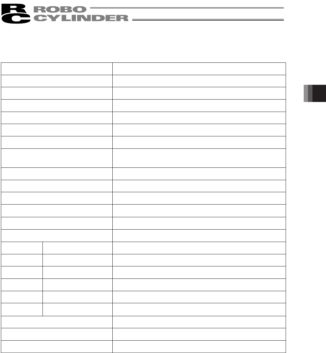
4.1 Controller
Specification item Description
Number of controlled axes 1 axis/unit
Supply voltage
24 VDC r10%
Supply current 2 A max.
Control method Weak field-magnet vector control (patent pending)
Positioning command Position number specification
Position number Maximum 16 points
Backup memory
Position number data and parameters are saved in nonvolatile
memory.
Serial E
2
PROM can be rewritten 100,000 times.
PIO 6 dedicated inputs/4 dedicated outputs
LED indicator Servo ON (green)/Alarm (red)
Communication RS485 1 channel (terminated externally)
Electromagnetic brake Release
The user must provide a selector switch. (Current consumption: 0.15 A
max.)
Extension cable length 10 m or less
Isolation strength
500 VDC, 10 M:
Environment Operating temperature
0 to 40qC
Operating humidity 85%RH or less (non-condensing)
Operating environment No contact with corrosive gases.
Storage temperature
-10 to 65qC
Storage humidity 90%RH or less (non-condensing)
Vibration resistance
10 to 57 Hz in XYZ directions / Pulsating amplitude: 0.035 mm
(continuous), 0.075 mm (intermittent)
Protection class IP20
Weight Approx. 32 g
External dimensions 109 W x 40 D (mm), printed circuit board