
Owner's manual


Table Of Contents
- Cover
- Please Read Before Use
- CAUTION
- CE Marking
- Table of Contents
- Safety Guide
- Caution in Handling
- 1. Overview
- 2. Installation
- 3. Wiring
- 3.1 Basic Structure
- 3.2 Configuration Using a SIO Converter
- 3.3 Configuration Using an Isolated PIO Terminal Block
- 3.4 Configuration Using Both SIO Converter and Isolated PIO Terminal Block
- 3.5 Specifications of I/O Signals
- 3.6 I/O Signals for PIO Pattern 1 [3 Points] (Air Cylinder)
- 3.7 I/O Signals for PIO Pattern 0 [8 Points]
- 3.8 I/O Signals for PIO Pattern 2 [16 Points] (Setting by Zone BoundaryParameters)
- 3.9 I/O Signals for PIO Pattern 3 [16 Points] (Setting in Zone Fields in thePosition Table)
- 3.10 Emergency-Stop Circuit
- 3.11 Extension Cable
- 4. Electrical Specifications
- 5. Data Entry
- 6. Operation in the “3 Points (Air Cylinder)” Mode
- 7. Operation in the “8 Points” and “16 Points” Modes
- 7.1 How to Start
- 7.2 Position Table and Parameter Settings Required for Operation
- 7.3 How to Execute Home Return
- 7.4 Home Return and Movement after Start (16 Points)
- 7.5 Positioning Mode (Back and Forth Movement between Two Points)
- 7.6 Push & Hold Mode
- 7.7 Speed Change during Movement
- 7.8 Operation at Different Acceleration and Deceleration Settings
- 7.9 Pause
- 7.10 Zone Signal
- 7.11 Incremental Moves
- 7.12 Notes on Incremental Mode
- 8. Parameter Settings
- 9. Troubleshooting
- 10. Maintenance and Inspection
- 11. Appendix
- Change History
68
3. Wiring
59
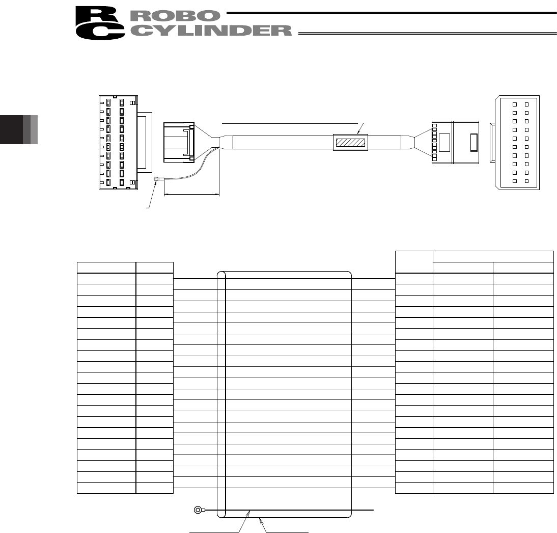
z Connectors on both ends (When using an isolated PIO terminal block)
10
9
8
7
6
5
4
3
2
1
10
9
8
7
6
5
4
3
2
1
A B
AMP
0-2100
B A
1
9
8
7
6
5
4
3
2
1
50
1A
1B
2A
2B
3A
3B
4A
4B
5A
5B
6A
6B
7A
7B
8A
8B
9A
9B
10A
10B
Orange (Red 1)
Orange (Black 1)
Light blue (Red 1)
Light blue (Black 1)
White (Red 1)
White (Black 1)
Yellow (Red 1)
Yellow (Black 1)
Pink (Red 1)
Pink (Black 1)
Orange (Red 2)
Orange (Black 2)
Light blue (Red 2)
Light blue (Black 2)
White (Red 2)
White (Black 2)
Yellow (Red 2)
Yellow (Black 2)
Pink (Red 2)
Pink (Black 2)
CN2
1A
1B
2A
2B
3A
3B
4A
4B
5A
5B
6A
6B
7A
7B
8A
8B
9A
9B
10A
10B
Orange (Red 1)
Orange (Black 1)
Light blue (Red 1)
Light blue (Black 1)
White (Red 1)
White (Black 1)
Yellow (Red 1)
Yellow (Black 1)
Pink (Red 1)
Pink (Black 1)
Orange (Red 2)
Orange (Black 2)
Light blue (Red 2)
Light blue (Black 2)
White (Red 2)
White (Black 2)
Yellow (Red 2)
Yellow (Black 2)
Pink (Red 2)
Pink (Black 2)
Terminal-block end
CN2
Actuator end
CN1
(J.S.T. Mfg.)
V0.5 - 3
Wire color
Pin name
Pin name
Wire color
CN1
Drain wire
Shielded wire
Housing: 1-1318115-9 (AMP)
Tab contact: 1318112-1
Housing: 1-1318118-9 (AMP)
Receptacle contact: 1318108-1
Orange (Red 1)
Orange (Black 1)
Gray (Red 1)
Gray (Black 1)
White (Red 1)
White (Black 1)
Yellow (Red 1)
Yellow (Black 1)
Pink (Red 1)
Pink (Black 1)
Orange (Red 2)
Orange (Black 2)
Gray (Red 2)
Gray (Black 2)
White (Red 2)
White (Black 2)
Yellow (Red 2)
Yellow (Black 2)
Pink (Red 2)
Pink (Black 2)
Standard cable Robot cable
CB-ERC-PWBIO * * *-H6 (Standard cable)
CB-ERC-PWBIO * * *-RB-H6
(
Robot cable
)