
Owner's manual


Table Of Contents
- Cover
- Please Read Before Use
- CAUTION
- CE Marking
- Table of Contents
- Safety Guide
- Caution in Handling
- 1. Overview
- 2. Installation
- 3. Wiring
- 3.1 Basic Structure
- 3.2 Configuration Using a SIO Converter
- 3.3 Configuration Using an Isolated PIO Terminal Block
- 3.4 Configuration Using Both SIO Converter and Isolated PIO Terminal Block
- 3.5 Specifications of I/O Signals
- 3.6 I/O Signals for PIO Pattern 1 [3 Points] (Air Cylinder)
- 3.7 I/O Signals for PIO Pattern 0 [8 Points]
- 3.8 I/O Signals for PIO Pattern 2 [16 Points] (Setting by Zone BoundaryParameters)
- 3.9 I/O Signals for PIO Pattern 3 [16 Points] (Setting in Zone Fields in thePosition Table)
- 3.10 Emergency-Stop Circuit
- 3.11 Extension Cable
- 4. Electrical Specifications
- 5. Data Entry
- 6. Operation in the “3 Points (Air Cylinder)” Mode
- 7. Operation in the “8 Points” and “16 Points” Modes
- 7.1 How to Start
- 7.2 Position Table and Parameter Settings Required for Operation
- 7.3 How to Execute Home Return
- 7.4 Home Return and Movement after Start (16 Points)
- 7.5 Positioning Mode (Back and Forth Movement between Two Points)
- 7.6 Push & Hold Mode
- 7.7 Speed Change during Movement
- 7.8 Operation at Different Acceleration and Deceleration Settings
- 7.9 Pause
- 7.10 Zone Signal
- 7.11 Incremental Moves
- 7.12 Notes on Incremental Mode
- 8. Parameter Settings
- 9. Troubleshooting
- 10. Maintenance and Inspection
- 11. Appendix
- Change History
50
3. Wiring
41
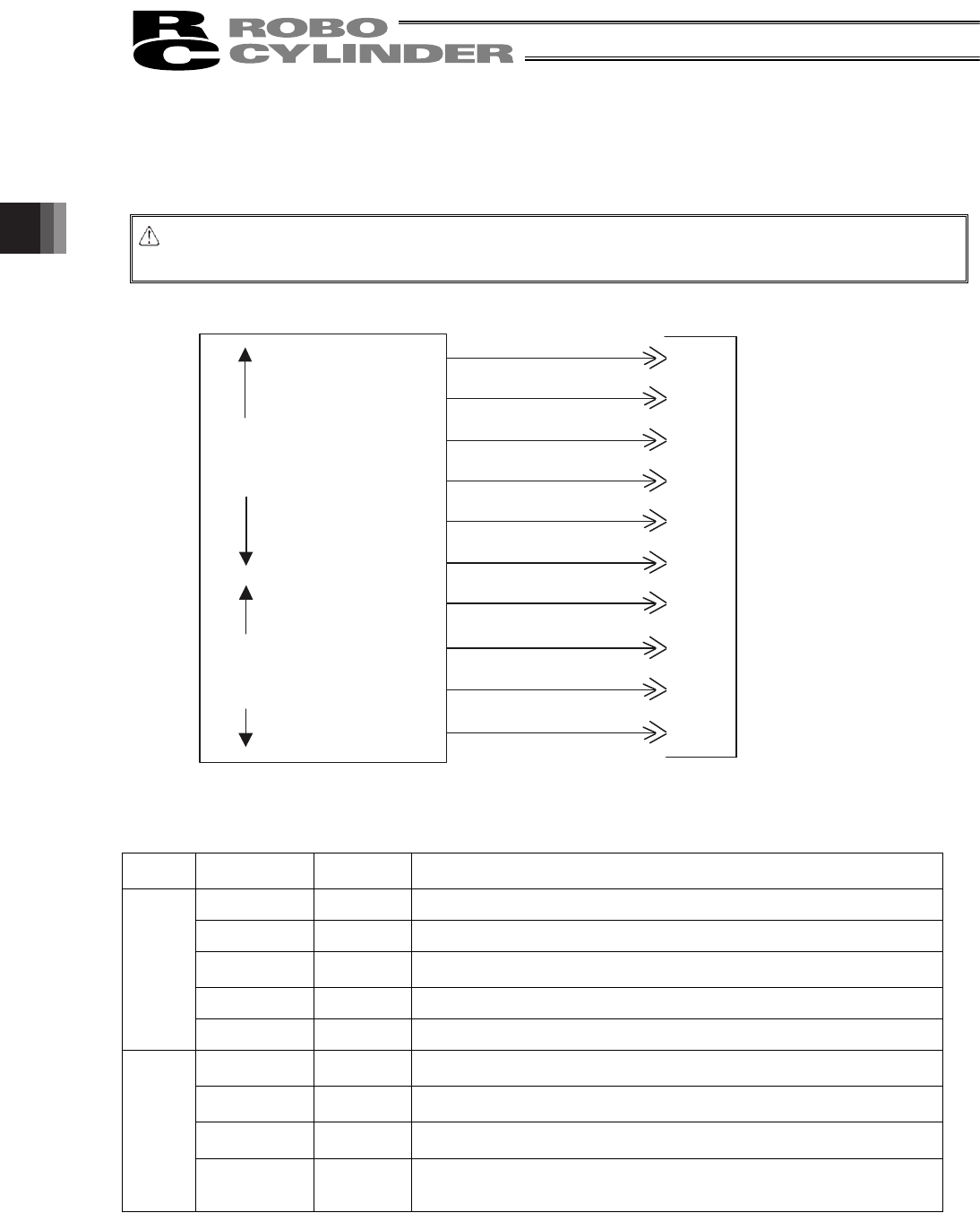
3.6 I/O Signals for PIO Pattern 1 [3 Points] (Air Cylinder)
The following description assumes that the actuator is used in place of an air cylinder.
The number of positioning points is limited to three, but a direct command input and a position complete output are
provided separately for the target position in line with the conventional practice of air cylinder control.
Caution: The factory setting is “8 points,” so set parameter No. 25 to “1.” The pause signal can be disabled in
parameter No. 15.
(Note) *STP and *ALM are always ON.
3.6.1 Explanation of I/O Signals
Category Signal name
Signal
abbreviation
Function overview
Rear end move ST0 The actuator starts moving to the rear end at the rise edge of the signal.
Front end move ST1 The actuator starts moving to the front end at the rise edge of the signal.
Intermediate
point move
ST2
The actuator starts moving to the intermediate point at the rise edge of the
signal.
*Pause *STP ON: The actuator can be moved, OFF: The actuator decelerates to a stop
Input
Alarm reset RES This signal resets the alarm output signal.
Rear end
complete
PE0 The signal turns ON when the actuator completes moving to the rear end.
Front end
complete
PE1 The signal turns ON when the actuator completes moving to the front end.
Intermediate
point complete
PE2
The signal turns ON when the actuator completes moving to the intermediate
point.
Output
*Alarm *ALM
This signal remains ON while the controller is operating properly, and turns
OFF when an alarm generates.
(Note) The signal remains ON while the motor drive power is cut off.
Orange (Red 2)
Orange (Black 2)
*Light blue (Red 2)
*Light blue (Black 2)
White (Red 2)
White (Black 2)
Yellow (Red 2)
Yellow (Black 2)
Pink (Red 2)
Pink (Black 2)
6A ST0
6B ST1
7A ST2
7B
8A RES
8B *STP
9A PE0
9B PE1
10A PE2
10B *ALM
Host system <PLC>
ERC2 actuator end
CN1 (Signal abbreviation)
Output
side
Input
side
Rear end move
Front end move
Intermediate point
move
Alarm reset
Pause
Rear end complete
Front end complete
Intermediate point
complete
Alarm
* Robot cable
Gray (Red 2)
Gray (Black 2)