
Owner's manual


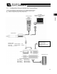


Table Of Contents
- Cover
- Please Read Before Use
- CAUTION
- CE Marking
- Table of Contents
- Safety Guide
- Caution in Handling
- 1. Overview
- 2. Installation
- 3. Wiring
- 3.1 Basic Structure
- 3.2 Configuration Using a SIO Converter
- 3.3 Configuration Using an Isolated PIO Terminal Block
- 3.4 Configuration Using Both SIO Converter and Isolated PIO Terminal Block
- 3.5 Specifications of I/O Signals
- 3.6 I/O Signals for PIO Pattern 1 [3 Points] (Air Cylinder)
- 3.7 I/O Signals for PIO Pattern 0 [8 Points]
- 3.8 I/O Signals for PIO Pattern 2 [16 Points] (Setting by Zone BoundaryParameters)
- 3.9 I/O Signals for PIO Pattern 3 [16 Points] (Setting in Zone Fields in thePosition Table)
- 3.10 Emergency-Stop Circuit
- 3.11 Extension Cable
- 4. Electrical Specifications
- 5. Data Entry
- 6. Operation in the “3 Points (Air Cylinder)” Mode
- 7. Operation in the “8 Points” and “16 Points” Modes
- 7.1 How to Start
- 7.2 Position Table and Parameter Settings Required for Operation
- 7.3 How to Execute Home Return
- 7.4 Home Return and Movement after Start (16 Points)
- 7.5 Positioning Mode (Back and Forth Movement between Two Points)
- 7.6 Push & Hold Mode
- 7.7 Speed Change during Movement
- 7.8 Operation at Different Acceleration and Deceleration Settings
- 7.9 Pause
- 7.10 Zone Signal
- 7.11 Incremental Moves
- 7.12 Notes on Incremental Mode
- 8. Parameter Settings
- 9. Troubleshooting
- 10. Maintenance and Inspection
- 11. Appendix
- Change History

42
3. Wiring
33
PC software
RS232C type <RCM-101-MW>
Optional
Teaching pendant <RCM-T>
Optional
Cable length: 5 m
Host system <PLC>
Connector
J1
ERC2 actuator
SIO converte
r
24-VDC control power supply
(
Emer
g
enc
y
-stop circuit
)
24-VDC control/motor power supply (2 A or more)
Brake release switch
Motor-power cutoff circuit
Insulated PIO terminal block
RS232C crossed cable
(provided by the user)
Insulated PIO terminal block
NPN, vertical <RCB-TU-PIO-A>
NPN, horizontal <RCB-TU-PIO-B>
PNP, vertical <RCB-TU-PIO-AP>
PNP, horizontal <RCB-TU-PIO-BP>
Extension cable
Standard cable <CB-ERC-PWBIO * * *-H6>
Robot cable <CB-ERC-PWBIO * * *-RB-H6>
Cable length: 1 m, 3 m, 5 m
SIO converter
V
ertical <RCB-TU-SIO-A>
H
orizontal <RCB-TU-SIO-B>
3.4 Configuration Using Both SIO Converter and Isolated PIO Terminal Block
Caution: Do not connect a teaching pendant and a PC at the same time. If both are connected at the same
time, a communication error (message level) will occur.