
Owner's manual
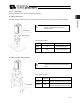
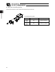


Table Of Contents
- Cover
- Please Read Before Use
- CAUTION
- CE Marking
- Table of Contents
- Safety Guide
- Caution in Handling
- 1. Overview
- 2. Installation
- 3. Wiring
- 3.1 Basic Structure
- 3.2 Configuration Using a SIO Converter
- 3.3 Configuration Using an Isolated PIO Terminal Block
- 3.4 Configuration Using Both SIO Converter and Isolated PIO Terminal Block
- 3.5 Specifications of I/O Signals
- 3.6 I/O Signals for PIO Pattern 1 [3 Points] (Air Cylinder)
- 3.7 I/O Signals for PIO Pattern 0 [8 Points]
- 3.8 I/O Signals for PIO Pattern 2 [16 Points] (Setting by Zone BoundaryParameters)
- 3.9 I/O Signals for PIO Pattern 3 [16 Points] (Setting in Zone Fields in thePosition Table)
- 3.10 Emergency-Stop Circuit
- 3.11 Extension Cable
- 4. Electrical Specifications
- 5. Data Entry
- 6. Operation in the “3 Points (Air Cylinder)” Mode
- 7. Operation in the “8 Points” and “16 Points” Modes
- 7.1 How to Start
- 7.2 Position Table and Parameter Settings Required for Operation
- 7.3 How to Execute Home Return
- 7.4 Home Return and Movement after Start (16 Points)
- 7.5 Positioning Mode (Back and Forth Movement between Two Points)
- 7.6 Push & Hold Mode
- 7.7 Speed Change during Movement
- 7.8 Operation at Different Acceleration and Deceleration Settings
- 7.9 Pause
- 7.10 Zone Signal
- 7.11 Incremental Moves
- 7.12 Notes on Incremental Mode
- 8. Parameter Settings
- 9. Troubleshooting
- 10. Maintenance and Inspection
- 11. Appendix
- Change History
33
3. Wiring
24
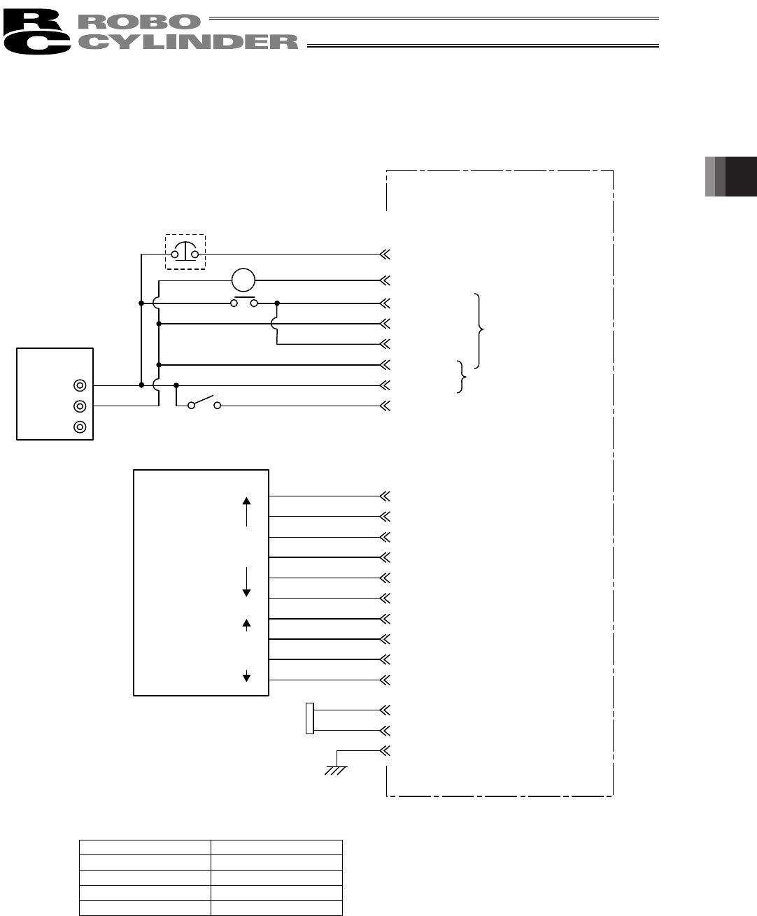
[2] When the control board is of the PNP specification [source type]
* In the case of a robot cable, the wire colors change as follows.
Wire color Pin number
Gray (Red 1) 2A
Gray (Black 1) 2B
Gray (Red 2) 7A
Gray (Black 2) 7B
(Note) To release the brake, connect a switch between BKR and 24 V and turn on the switch.
24V
0V
FG
SGA
SGB
6A
6B
EMS1
2A
EMS2
2B
MPI
4A
GND
4B
MPI
5A
GND
5B
24V
3A
BKR3B
7A
7B
8A
8B
9A
9B
10A
10B
1A
1B
MC
CN1
CN2
FG
Orange (Red 2)
Orange (Black 2)
*Light blue (Red 2)
*Light blue (Black 2)
White (Red 2)
White (Black 2)
Yellow (Red 2)
Yellow (Black 2)
Pink (Red 2)
Pink (Black 2)
Orange (Red 1)
Orange (Black 1)
Serial communication
Ground
EMG signal
Input power supply
(2 A or more)
Brake release
switch
ERC2 actuator
Contact output for EMG
switch on teaching pendant
Motor drive power supply
Control power supply
OFF when the brake is
controlled by the controller,
or ON when the brake is
released
(Applicable to an actuator
with brake)
Host system
<PLC>
Output
side
(Not used)
*Light blue (Red 1)
*Light blue (Black 1)
Yellow (Red 1)
Yellow (Black 1)
Pink (Red 1)
Pink (Black 1)
White (Red 1)
White (Black 1)
I/O interface
(Refer to the I/O connections for each
PIO pattern)
(Note)
Relay
Input
side
60 mA max.