
Owner's manual


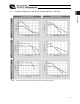


Table Of Contents
- Cover
- Please Read Before Use
- CAUTION
- CE Marking
- Table of Contents
- Safety Guide
- Caution in Handling
- 1. Overview
- 2. Installation
- 3. Wiring
- 3.1 Basic Structure
- 3.2 Configuration Using a SIO Converter
- 3.3 Configuration Using an Isolated PIO Terminal Block
- 3.4 Configuration Using Both SIO Converter and Isolated PIO Terminal Block
- 3.5 Specifications of I/O Signals
- 3.6 I/O Signals for PIO Pattern 1 [3 Points] (Air Cylinder)
- 3.7 I/O Signals for PIO Pattern 0 [8 Points]
- 3.8 I/O Signals for PIO Pattern 2 [16 Points] (Setting by Zone BoundaryParameters)
- 3.9 I/O Signals for PIO Pattern 3 [16 Points] (Setting in Zone Fields in thePosition Table)
- 3.10 Emergency-Stop Circuit
- 3.11 Extension Cable
- 4. Electrical Specifications
- 5. Data Entry
- 6. Operation in the “3 Points (Air Cylinder)” Mode
- 7. Operation in the “8 Points” and “16 Points” Modes
- 7.1 How to Start
- 7.2 Position Table and Parameter Settings Required for Operation
- 7.3 How to Execute Home Return
- 7.4 Home Return and Movement after Start (16 Points)
- 7.5 Positioning Mode (Back and Forth Movement between Two Points)
- 7.6 Push & Hold Mode
- 7.7 Speed Change during Movement
- 7.8 Operation at Different Acceleration and Deceleration Settings
- 7.9 Pause
- 7.10 Zone Signal
- 7.11 Incremental Moves
- 7.12 Notes on Incremental Mode
- 8. Parameter Settings
- 9. Troubleshooting
- 10. Maintenance and Inspection
- 11. Appendix
- Change History
14
1. Overview
6
Load Applied to the Actuator
(1) Slider type
x Keep the load applied to the slider below the value stated in the applicable specification item.
In particular, pay attention to the moment applied to the slider, allowable overhang length and payload capacity.
x If the slider is used in an overhang application with the load extending in the Y-axis direction, keep moments Ma
and Mc to one-half the rated moment or less to prevent the base from deforming.
(2) Rod type
x Keep the load applied to the rod below the value specified in the catalog.
x Make sure the center of the rod axis corresponds to the moving direction of the load.
x Application of lateral load may cause an actuator damage or breakdown.
x If the rod is to be subjected to lateral load, provide a guide or other support in the
moving direction of the load.
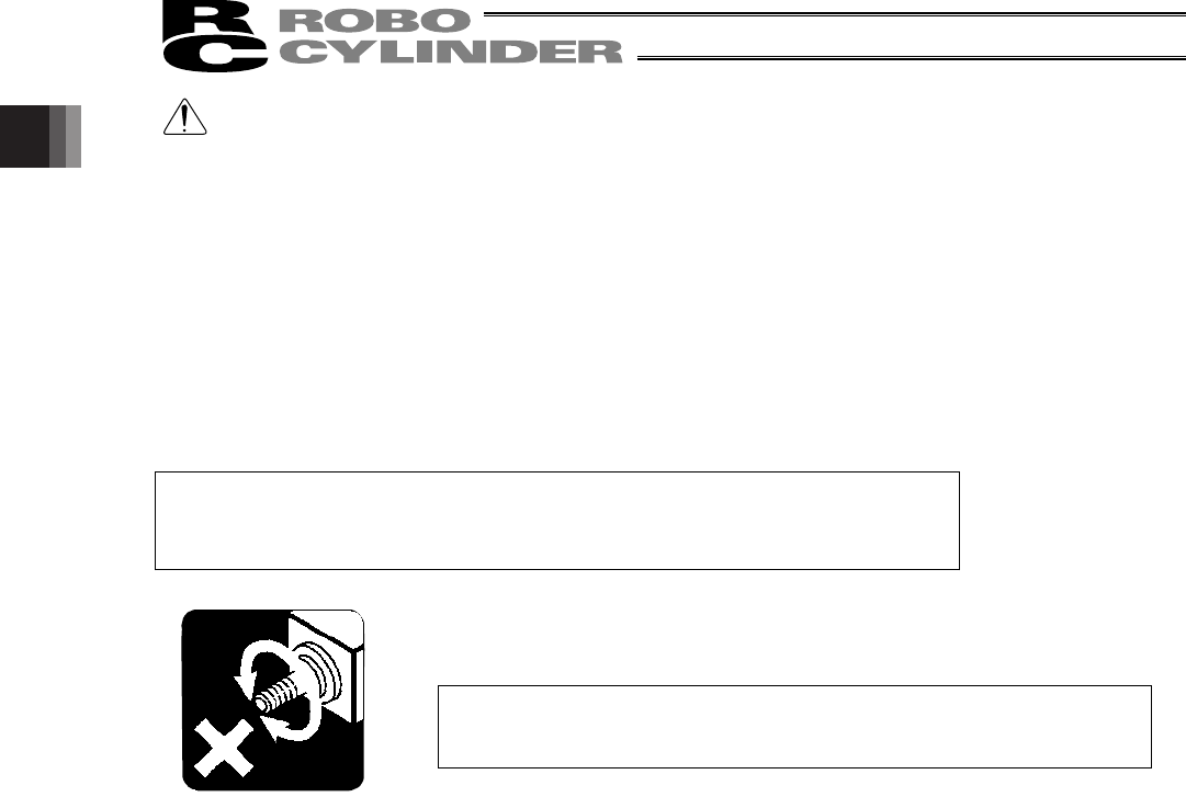
x Do not apply rotating torque to the rod (slide shaft).
* It will result in internal damages.
When tightening the nut at the tip of the rod, secure the rod using a wrench of
size 13 (RA6C type) or 17 (RA7C type).
1.3.3 The sound pressure level of this product does not exceed 70 dB.