
Owner's manual


Table Of Contents
- Cover
- Please Read Before Use
- CAUTION
- CE Marking
- Table of Contents
- Safety Guide
- Caution in Handling
- 1. Overview
- 2. Installation
- 3. Wiring
- 3.1 Basic Structure
- 3.2 Configuration Using a SIO Converter
- 3.3 Configuration Using an Isolated PIO Terminal Block
- 3.4 Configuration Using Both SIO Converter and Isolated PIO Terminal Block
- 3.5 Specifications of I/O Signals
- 3.6 I/O Signals for PIO Pattern 1 [3 Points] (Air Cylinder)
- 3.7 I/O Signals for PIO Pattern 0 [8 Points]
- 3.8 I/O Signals for PIO Pattern 2 [16 Points] (Setting by Zone BoundaryParameters)
- 3.9 I/O Signals for PIO Pattern 3 [16 Points] (Setting in Zone Fields in thePosition Table)
- 3.10 Emergency-Stop Circuit
- 3.11 Extension Cable
- 4. Electrical Specifications
- 5. Data Entry
- 6. Operation in the “3 Points (Air Cylinder)” Mode
- 7. Operation in the “8 Points” and “16 Points” Modes
- 7.1 How to Start
- 7.2 Position Table and Parameter Settings Required for Operation
- 7.3 How to Execute Home Return
- 7.4 Home Return and Movement after Start (16 Points)
- 7.5 Positioning Mode (Back and Forth Movement between Two Points)
- 7.6 Push & Hold Mode
- 7.7 Speed Change during Movement
- 7.8 Operation at Different Acceleration and Deceleration Settings
- 7.9 Pause
- 7.10 Zone Signal
- 7.11 Incremental Moves
- 7.12 Notes on Incremental Mode
- 8. Parameter Settings
- 9. Troubleshooting
- 10. Maintenance and Inspection
- 11. Appendix
- Change History
10
1. Overview
2
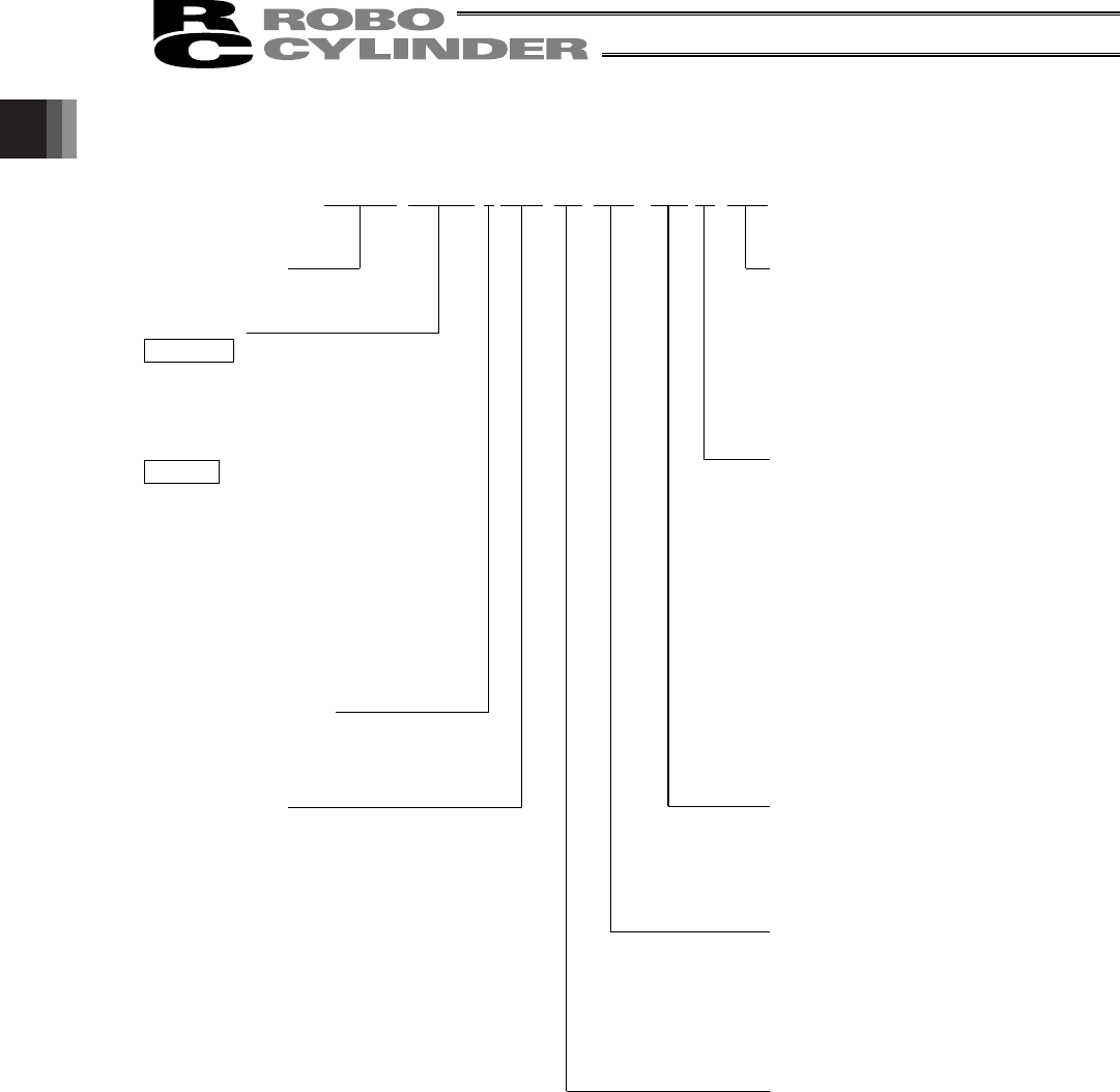
(5&6$&,3013610
<Series name>
<Type>
Slider type
x SA6C
x SA7C
Rod type
x RA6C
x RA7C
x RGS6C
x RGS7C
x RGD6C
x RGD7C
<Encoder type>
I: Incremental
<Motor type>
PM: Pulse motor
<Options>
Blank: No option
B: With brake
NM: Reversed-home specification
FT: Foot bracket (Specified only
for rod types.)
<Extension cable length>
Blank: No cable
P: 1 m
S: 3 m
M: 5 m
X: Length specification (Example) X08 = 8 m
R: Robot cable specification
RW: Connectors on both ends
Robot cable / Connectors on both ends
<Stroke>
50 to 600 mm
(Standard lengths are multiples of 50 mm.)
(Example) 100 = 100 mm
<I/O signal pattern>
NP: PIO NPN (sink type)
PN: PIO PNP (source type)
<Ball screw lead>
16: 16 mm
12: 12 mm
8: 8 mm
6: 6 mm
4: 4 mm
3: 3 mm
1.2 Meaning of the Model Number