
Owner's manual


Table Of Contents
- Cover
- Please Read Before Use
- CAUTION
- CE Marking
- Table of Contents
- Safety Guide
- Caution in Handling
- 1. Overview
- 2. Installation
- 3. Wiring
- 3.1 Basic Structure
- 3.2 Configuration Using a SIO Converter
- 3.3 Configuration Using an Isolated PIO Terminal Block
- 3.4 Configuration Using Both SIO Converter and Isolated PIO Terminal Block
- 3.5 Specifications of I/O Signals
- 3.6 I/O Signals for PIO Pattern 1 [3 Points] (Air Cylinder)
- 3.7 I/O Signals for PIO Pattern 0 [8 Points]
- 3.8 I/O Signals for PIO Pattern 2 [16 Points] (Setting by Zone BoundaryParameters)
- 3.9 I/O Signals for PIO Pattern 3 [16 Points] (Setting in Zone Fields in thePosition Table)
- 3.10 Emergency-Stop Circuit
- 3.11 Extension Cable
- 4. Electrical Specifications
- 5. Data Entry
- 6. Operation in the “3 Points (Air Cylinder)” Mode
- 7. Operation in the “8 Points” and “16 Points” Modes
- 7.1 How to Start
- 7.2 Position Table and Parameter Settings Required for Operation
- 7.3 How to Execute Home Return
- 7.4 Home Return and Movement after Start (16 Points)
- 7.5 Positioning Mode (Back and Forth Movement between Two Points)
- 7.6 Push & Hold Mode
- 7.7 Speed Change during Movement
- 7.8 Operation at Different Acceleration and Deceleration Settings
- 7.9 Pause
- 7.10 Zone Signal
- 7.11 Incremental Moves
- 7.12 Notes on Incremental Mode
- 8. Parameter Settings
- 9. Troubleshooting
- 10. Maintenance and Inspection
- 11. Appendix
- Change History
161
11. Appendix
Appendix
11.
Appendix
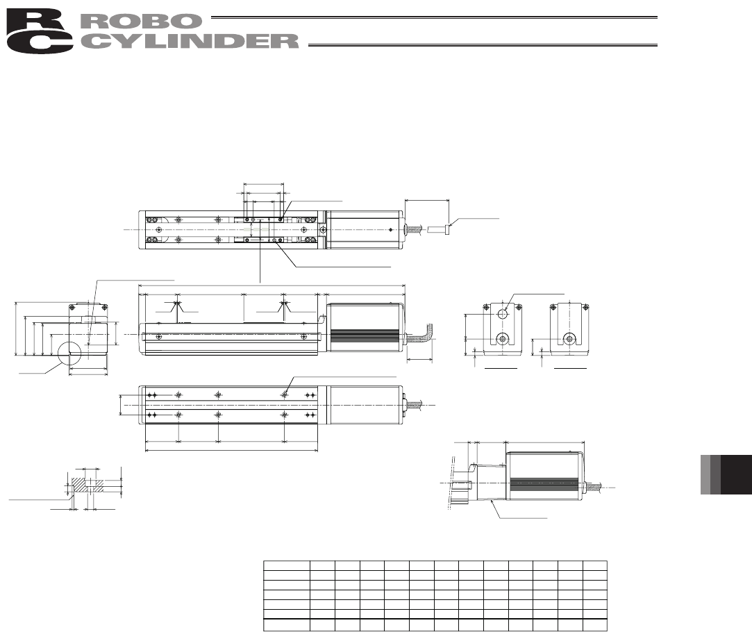
11.1 External Dimensions
11.1.1 ERC2-SA6C
50.9
2.5
49.1
2.3
37.5
25
13.5
118.5
80.6
30
A
50 B 50
60
5 50 5
9
9
32
32
S.E.
M.E.
L
10
Stroke 60
59
50
48.5
58
13.5
43.5 118.5
22
31
37.4
(300)
(6)
25
36
55
p
0.02
(6)
N
s
100
P
PIO type SIO type
M.E.*2
Stroke 50 100 150 200 250 300 350 400 450 500 550 600
L
A
B
N
S
Weight [kg]
352
210
10
1
6
1.9
402
260
60
1
6
2.0
452
310
10
2
8
2.1
502
360
60
2
8
2.3
552
410
10
3
10
2.4
602
460
60
3
10
2.6
652
510
10
4
12
2.7
702
560
60
4
12
2.8
752
610
10
5
14
3.0
802
660
60
5
14
3.1
852
710
10
6
16
3.3
902
760
60
6
16
3.4
4.5
4
F
8
1.5
F
4.5
4.5
Datum Surface
DETAIL : A
(Attachment Hole and Datum Surface)
Home
Secure
at least
100
(Reamer Pitch
Tolerance
p
0.02)
2-
F
5
H
7 Reamed, Depth 10
4-M5 Depth 10
Cable joint
connector
S E : Stroke End
ME : Mechanical End
Teaching Port
Brake unit
Ma Moment
Offset Datum Position
Part A
S-4.5 Drilled Hole,
F
8 Counter Boring Depth 4.5
*There is no Teaching
Port for SIO Type.
Appearance Figure for Brake-equipped Type
*Brake-equipped type is longer in 43.5mm and
weight heavier in 0.5kg than the standard type.