
Owner's manual


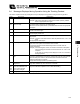


Table Of Contents
- Cover
- Please Read Before Use
- CAUTION
- CE Marking
- Table of Contents
- Safety Guide
- Caution in Handling
- 1. Overview
- 2. Installation
- 3. Wiring
- 3.1 Basic Structure
- 3.2 Configuration Using a SIO Converter
- 3.3 Configuration Using an Isolated PIO Terminal Block
- 3.4 Configuration Using Both SIO Converter and Isolated PIO Terminal Block
- 3.5 Specifications of I/O Signals
- 3.6 I/O Signals for PIO Pattern 1 [3 Points] (Air Cylinder)
- 3.7 I/O Signals for PIO Pattern 0 [8 Points]
- 3.8 I/O Signals for PIO Pattern 2 [16 Points] (Setting by Zone BoundaryParameters)
- 3.9 I/O Signals for PIO Pattern 3 [16 Points] (Setting in Zone Fields in thePosition Table)
- 3.10 Emergency-Stop Circuit
- 3.11 Extension Cable
- 4. Electrical Specifications
- 5. Data Entry
- 6. Operation in the “3 Points (Air Cylinder)” Mode
- 7. Operation in the “8 Points” and “16 Points” Modes
- 7.1 How to Start
- 7.2 Position Table and Parameter Settings Required for Operation
- 7.3 How to Execute Home Return
- 7.4 Home Return and Movement after Start (16 Points)
- 7.5 Positioning Mode (Back and Forth Movement between Two Points)
- 7.6 Push & Hold Mode
- 7.7 Speed Change during Movement
- 7.8 Operation at Different Acceleration and Deceleration Settings
- 7.9 Pause
- 7.10 Zone Signal
- 7.11 Incremental Moves
- 7.12 Notes on Incremental Mode
- 8. Parameter Settings
- 9. Troubleshooting
- 10. Maintenance and Inspection
- 11. Appendix
- Change History

147
9. Troubleshooting
138
(2) Cold-start level alarms
Code Error name Cause/Action
B8 Excitation detection error This controller detects excited phase when the servo is turned on for the first time
after a power on. This alarm indicates that the specified encoder signal level
cannot be detected after the specified period of excitation.
Cause: [1] Loose or disconnected connector of the motor extension cable
[2] The brake cannot be released (if the actuator is equipped with a
brake).
[3] A large load is applied due to an external force.
[4] The power was turned on when the actuator was contacting a
mechanical end.
[5] The slide resistance of the actuator itself is large.
Action: [1] Check the wiring condition of the motor extension cable.
[2] Check the wiring condition of the brake cable, and also turn on/off
the brake release switch to check if a “click” sound is heard.
[3] Check for abnormality in the assembly condition of mechanical
parts.
Increasing the value of parameter No. 29 (Excited-phase signal
detection time) may be effective.
If you wish to change the parameter setting, contact IAI beforehand.
[4] Move the actuator away from the mechanical end, and then turn on
the power again.
Alternatively, change the value of parameter No. 28 (Default
direction of excited-phase signal detection).
[5] If the load is normal, turn off the power and move the actuator by
hand to check the slide resistance.
If the actuator is suspected to be faulty, please contact IAI.
D8 Deviation overflow The position deviation counter has overflowed.
Cause: [1] The speed dropped due to external force, etc., while the actuator
was moving.
[2] Unstable excitation detection operation after the power has been
turned on
Action: [1] Check the load condition, such as if the work part is contacting any
object around it or the brake is released, and remove the identified
cause.
[2] An overload condition is suspected, so review the loading mass.
After appropriate adjustment has been made, reconnect the power
and perform home return.
DC Out-of-range error in
push & hold operation
This alarm occurs when the actuator was pushed back to the target position after
completion of push & hold operation, due to a strong push-back force of the work
part.
Review the overall settings of the system.