
Owner's manual


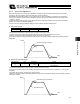


Table Of Contents
- Cover
- Please Read Before Use
- CAUTION
- CE Marking
- Table of Contents
- Safety Guide
- Caution in Handling
- 1. Overview
- 2. Installation
- 3. Wiring
- 3.1 Basic Structure
- 3.2 Configuration Using a SIO Converter
- 3.3 Configuration Using an Isolated PIO Terminal Block
- 3.4 Configuration Using Both SIO Converter and Isolated PIO Terminal Block
- 3.5 Specifications of I/O Signals
- 3.6 I/O Signals for PIO Pattern 1 [3 Points] (Air Cylinder)
- 3.7 I/O Signals for PIO Pattern 0 [8 Points]
- 3.8 I/O Signals for PIO Pattern 2 [16 Points] (Setting by Zone BoundaryParameters)
- 3.9 I/O Signals for PIO Pattern 3 [16 Points] (Setting in Zone Fields in thePosition Table)
- 3.10 Emergency-Stop Circuit
- 3.11 Extension Cable
- 4. Electrical Specifications
- 5. Data Entry
- 6. Operation in the “3 Points (Air Cylinder)” Mode
- 7. Operation in the “8 Points” and “16 Points” Modes
- 7.1 How to Start
- 7.2 Position Table and Parameter Settings Required for Operation
- 7.3 How to Execute Home Return
- 7.4 Home Return and Movement after Start (16 Points)
- 7.5 Positioning Mode (Back and Forth Movement between Two Points)
- 7.6 Push & Hold Mode
- 7.7 Speed Change during Movement
- 7.8 Operation at Different Acceleration and Deceleration Settings
- 7.9 Pause
- 7.10 Zone Signal
- 7.11 Incremental Moves
- 7.12 Notes on Incremental Mode
- 8. Parameter Settings
- 9. Troubleshooting
- 10. Maintenance and Inspection
- 11. Appendix
- Change History

144
9. Troubleshooting
135
9.2 Alarm Level Classification
Alarms are classified into two levels according to the symptoms they represent.
Alarm level LED color *ALM signal What happens when alarm generates How to reset
Operation
cancellation
Red OFF The actuator decelerates to a stop and
then the servo turns OFF.
See below.
Cold start Red OFF The actuator decelerates to a stop and
then the servo turns OFF.
Reconnect the power or
reset the software.
(Note) The *ALM output signal is a contact-b signal.
When the power is on, this signal remains ON while the actuator is normal, and turns OFF if an alarm has
occurred.
When the power is cut off, the signal remains OFF. However, it cannot be used as a contact-b interlock
signal.
9.2.1 How to Reset Alarms
PIO pattern = 8 points or 16 points
Cut off the motor drive power, and then input a start signal (CSTR) for at least 6 msec.
After the *ALM signal has turned ON, confirm that it is ON, turn the CSTR signal OFF, and then restore the motor
drive power.
PIO pattern = 3 points
Input an alarm reset signal (RES) for at least 6 msec.
After the *ALM signal has turned ON, confirm that it is ON and then turn the RES signal OFF.
Caution: Before resetting an alarm, always identify and remove the cause of the alarm.
If the cause cannot be removed or the alarm still persists after removing the cause, contact IAI.
If the same error occurs again after resetting the alarm, the problem that caused the alarm in the first
place is still present.
Motor drive power
Start input signal (CSTR)
A
larm output signal (*ALM)
Supplied Cut off
At least 6 msec
Alarm present
Alarm reset
At least 6 msec
Alarm reset input signal (RES)
Alarm output signal (*ALM)
Alarm present
Alarm reset