
Owner's manual


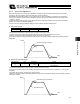


Table Of Contents
- Cover
- Please Read Before Use
- CAUTION
- CE Marking
- Table of Contents
- Safety Guide
- Caution in Handling
- 1. Overview
- 2. Installation
- 3. Wiring
- 3.1 Basic Structure
- 3.2 Configuration Using a SIO Converter
- 3.3 Configuration Using an Isolated PIO Terminal Block
- 3.4 Configuration Using Both SIO Converter and Isolated PIO Terminal Block
- 3.5 Specifications of I/O Signals
- 3.6 I/O Signals for PIO Pattern 1 [3 Points] (Air Cylinder)
- 3.7 I/O Signals for PIO Pattern 0 [8 Points]
- 3.8 I/O Signals for PIO Pattern 2 [16 Points] (Setting by Zone BoundaryParameters)
- 3.9 I/O Signals for PIO Pattern 3 [16 Points] (Setting in Zone Fields in thePosition Table)
- 3.10 Emergency-Stop Circuit
- 3.11 Extension Cable
- 4. Electrical Specifications
- 5. Data Entry
- 6. Operation in the “3 Points (Air Cylinder)” Mode
- 7. Operation in the “8 Points” and “16 Points” Modes
- 7.1 How to Start
- 7.2 Position Table and Parameter Settings Required for Operation
- 7.3 How to Execute Home Return
- 7.4 Home Return and Movement after Start (16 Points)
- 7.5 Positioning Mode (Back and Forth Movement between Two Points)
- 7.6 Push & Hold Mode
- 7.7 Speed Change during Movement
- 7.8 Operation at Different Acceleration and Deceleration Settings
- 7.9 Pause
- 7.10 Zone Signal
- 7.11 Incremental Moves
- 7.12 Notes on Incremental Mode
- 8. Parameter Settings
- 9. Troubleshooting
- 10. Maintenance and Inspection
- 11. Appendix
- Change History
142
8. Parameter Settings
133
z Speed loop integral gain
Parameter No. Unit Input range Default
32 --- 1 ~ 217270
Set individually in accordance with the actuator
characteristics.
This parameter is used to determine the response of the speed control loop.
Reducing the set value lowers the response to speed commands, meaning that the reactive force that generates in
response to load change becomes smaller. A smaller set value also results in poorer compliance with position
commands, causing the positioning time to become longer.
If the set value is excessive, on the other hand, the actuator may overshoot or oscillate, rendering the mechanical
parts more prone to vibration.
z Torque filter time constant
Parameter No. Unit Input range Default
33 --- 1 ~ 2500
Set individually in accordance with the actuator
characteristics.
This parameter determines the filter time constant for torque commands.
If the resonance frequency of the machine is smaller than the response frequency of the servo loop, the motor
vibrates.
This mechanical resonance can be suppressed by increasing the value set in this parameter.
However, increasing the value excessively may reduce the stability of control.
Speed
Set value is high (overshoot)
Set value is low
Time