
Owner's manual


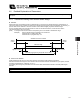


Table Of Contents
- Cover
- Please Read Before Use
- CAUTION
- CE Marking
- Table of Contents
- Safety Guide
- Caution in Handling
- 1. Overview
- 2. Installation
- 3. Wiring
- 3.1 Basic Structure
- 3.2 Configuration Using a SIO Converter
- 3.3 Configuration Using an Isolated PIO Terminal Block
- 3.4 Configuration Using Both SIO Converter and Isolated PIO Terminal Block
- 3.5 Specifications of I/O Signals
- 3.6 I/O Signals for PIO Pattern 1 [3 Points] (Air Cylinder)
- 3.7 I/O Signals for PIO Pattern 0 [8 Points]
- 3.8 I/O Signals for PIO Pattern 2 [16 Points] (Setting by Zone BoundaryParameters)
- 3.9 I/O Signals for PIO Pattern 3 [16 Points] (Setting in Zone Fields in thePosition Table)
- 3.10 Emergency-Stop Circuit
- 3.11 Extension Cable
- 4. Electrical Specifications
- 5. Data Entry
- 6. Operation in the “3 Points (Air Cylinder)” Mode
- 7. Operation in the “8 Points” and “16 Points” Modes
- 7.1 How to Start
- 7.2 Position Table and Parameter Settings Required for Operation
- 7.3 How to Execute Home Return
- 7.4 Home Return and Movement after Start (16 Points)
- 7.5 Positioning Mode (Back and Forth Movement between Two Points)
- 7.6 Push & Hold Mode
- 7.7 Speed Change during Movement
- 7.8 Operation at Different Acceleration and Deceleration Settings
- 7.9 Pause
- 7.10 Zone Signal
- 7.11 Incremental Moves
- 7.12 Notes on Incremental Mode
- 8. Parameter Settings
- 9. Troubleshooting
- 10. Maintenance and Inspection
- 11. Appendix
- Change History

136
8. Parameter Settings
127
z Push speed
This parameter defines the push speed to be applied after the actuator reaches the target position in push & hold
operation.
Before the shipment, this speed has been set to a default value appropriate for the characteristics of the actuator.
Set an appropriate speed in parameter No. 34 by considering the material and shape of the work part, and so on.
Take note that the maximum speed is limited to 20 [mm/sec] even on high-speed types. Use the actuator at push
speeds not exceeding this level.
Caution: It is recommended that you set the push speed to 5 mm/sec or above to minimize the negative effect
of push force variation.
z Push & hold stop judgment period
This parameter is used as a condition for determining that the work part was contacted and the push & hold operation
has completed.
As for the specific method of judgment, the push & hold operation is deemed to have completed if the current-limiting
value set in the position table has been retained for the time set in parameter No. 6.
Set an optimal time matching the current-limiting value, by considering the material and shape of the work part, and so
on.
The minimum setting unit is “1 [msec],” while the maximum value is “9999 [msec].” The factory setting is “255 [msec].”
(Note) If the work part has shifted and the current has changed during the push & hold judgment, the judgment
follows the timing chart shown below. This example assumes a judgment period of 255 msec.
After reaching the push current, it is maintained for 200 msec. The current drops during the subsequent 20-msec
period, and accordingly the count is decremented by 20. Therefore, when the operation is resumed the count will start
from 180. Since the count will reach 255 after 75 msec at the push current, the controller will determine that the push
& hold operation has completed.
In this example, the total judgment period is 295 msec.
Push current
20 msec
Start position
Target position
Counting starts
Counting continues until 200
Count is decremented to 180
Count is incremented to 255
Judgment of push & hold completion
75 msec
Speed
Load
Positioning band
Push speed