
Owner's manual


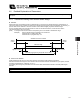


Table Of Contents
- Cover
- Please Read Before Use
- CAUTION
- CE Marking
- Table of Contents
- Safety Guide
- Caution in Handling
- 1. Overview
- 2. Installation
- 3. Wiring
- 3.1 Basic Structure
- 3.2 Configuration Using a SIO Converter
- 3.3 Configuration Using an Isolated PIO Terminal Block
- 3.4 Configuration Using Both SIO Converter and Isolated PIO Terminal Block
- 3.5 Specifications of I/O Signals
- 3.6 I/O Signals for PIO Pattern 1 [3 Points] (Air Cylinder)
- 3.7 I/O Signals for PIO Pattern 0 [8 Points]
- 3.8 I/O Signals for PIO Pattern 2 [16 Points] (Setting by Zone BoundaryParameters)
- 3.9 I/O Signals for PIO Pattern 3 [16 Points] (Setting in Zone Fields in thePosition Table)
- 3.10 Emergency-Stop Circuit
- 3.11 Extension Cable
- 4. Electrical Specifications
- 5. Data Entry
- 6. Operation in the “3 Points (Air Cylinder)” Mode
- 7. Operation in the “8 Points” and “16 Points” Modes
- 7.1 How to Start
- 7.2 Position Table and Parameter Settings Required for Operation
- 7.3 How to Execute Home Return
- 7.4 Home Return and Movement after Start (16 Points)
- 7.5 Positioning Mode (Back and Forth Movement between Two Points)
- 7.6 Push & Hold Mode
- 7.7 Speed Change during Movement
- 7.8 Operation at Different Acceleration and Deceleration Settings
- 7.9 Pause
- 7.10 Zone Signal
- 7.11 Incremental Moves
- 7.12 Notes on Incremental Mode
- 8. Parameter Settings
- 9. Troubleshooting
- 10. Maintenance and Inspection
- 11. Appendix
- Change History
134
8. Parameter Settings
125
z Default direction of excited-phase signal detection
When the servo is turned on for the first time after a power on, excited phase is detected. This parameter defines the
direction of this detection.
The parameter need not be changed in normal conditions. In certain situations, such as when the actuator was
contacting a mechanical end or obstacle when the power was turned on and cannot be moved by hand, change the
direction that allows the motor to operate smoothly.
To do this, set parameter No. 28 to “0” or “1.” If the detection direction should be the same as the home return
direction, specify the same value currently set in parameter No. 5 (Home return direction).
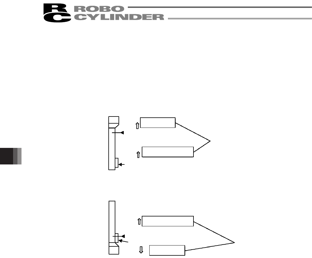
To set a direction opposite to the home return direction, specify the value different from the one currently set in
parameter No. 5 (Home return direction).
(Example 1) Power was turned on when the slider was contacting the bottom mechanical end in a configuration
where the actuator is installed vertically with the motor at the top.
(Example 2) Power was turned on when the slider was contacting the bottom mechanical end in a configuration
where the actuator is installed vertically with the motor at the bottom.
z Excited-phase signal detection time
When the servo is turned on for the first time after a power on, excited phase is detected. This parameter defines the
time of this detection.
The parameter need not be changed in normal conditions, because a detection time appropriate for the standard
specification of the actuator has been set at the factory.
Should an excitation detection error or abnormal operation occur when the servo is turned on for the first time after a
power on, one remedial action that can be taken is to change the detection time set in parameter No. 29.
If you wish to change this parameter, contact IAI beforehand.
z Safety speed
This parameter defines the feed speed to be applied during manual operation.
The factory setting is “100 [mm/sec].”
To change this speed, set an optimal value in parameter No. 35.
Take note that the maximum speed is 250 mm/sec and that you should set a speed not exceeding this value.
Top
Bottom
Home position
Home return
direction
Direction of excited-
phase si
g
nal detection
The slider is contacting the bottom mechanical end.
Set the same value.
Top
Bottom
Home position
Home return
direction
The slider is contacting the bottom mechanical
end.
Direction of excited-
p
hase si
g
nal detection
Set different values.