
Owner's manual


Table Of Contents
- Cover
- Please Read Before Use
- CAUTION
- CE Marking
- Table of Contents
- Safety Guide
- Caution in Handling
- 1. Overview
- 2. Installation
- 3. Wiring
- 3.1 Basic Structure
- 3.2 Configuration Using a SIO Converter
- 3.3 Configuration Using an Isolated PIO Terminal Block
- 3.4 Configuration Using Both SIO Converter and Isolated PIO Terminal Block
- 3.5 Specifications of I/O Signals
- 3.6 I/O Signals for PIO Pattern 1 [3 Points] (Air Cylinder)
- 3.7 I/O Signals for PIO Pattern 0 [8 Points]
- 3.8 I/O Signals for PIO Pattern 2 [16 Points] (Setting by Zone BoundaryParameters)
- 3.9 I/O Signals for PIO Pattern 3 [16 Points] (Setting in Zone Fields in thePosition Table)
- 3.10 Emergency-Stop Circuit
- 3.11 Extension Cable
- 4. Electrical Specifications
- 5. Data Entry
- 6. Operation in the “3 Points (Air Cylinder)” Mode
- 7. Operation in the “8 Points” and “16 Points” Modes
- 7.1 How to Start
- 7.2 Position Table and Parameter Settings Required for Operation
- 7.3 How to Execute Home Return
- 7.4 Home Return and Movement after Start (16 Points)
- 7.5 Positioning Mode (Back and Forth Movement between Two Points)
- 7.6 Push & Hold Mode
- 7.7 Speed Change during Movement
- 7.8 Operation at Different Acceleration and Deceleration Settings
- 7.9 Pause
- 7.10 Zone Signal
- 7.11 Incremental Moves
- 7.12 Notes on Incremental Mode
- 8. Parameter Settings
- 9. Troubleshooting
- 10. Maintenance and Inspection
- 11. Appendix
- Change History
132
8. Parameter Settings
123
z Home return offset
The controller is shipped from the factory with an optimal value set in parameter No. 22, so the distance from each
mechanical end to the home becomes uniform.
The minimum setting unit is “0.01 [mm].”
The home return offset can be adjusted in the following conditions:
[1] Want to align the actuator home and the system’s mechanical home after the actuator has been assembled into
the system
[2] Want to set a new home after reversing the factory-set home direction
[3] Want to eliminate a slight deviation generated after replacing the actuator
Caution: If the home return offset has been changed, the soft limit parameters must also be adjusted
accordingly.
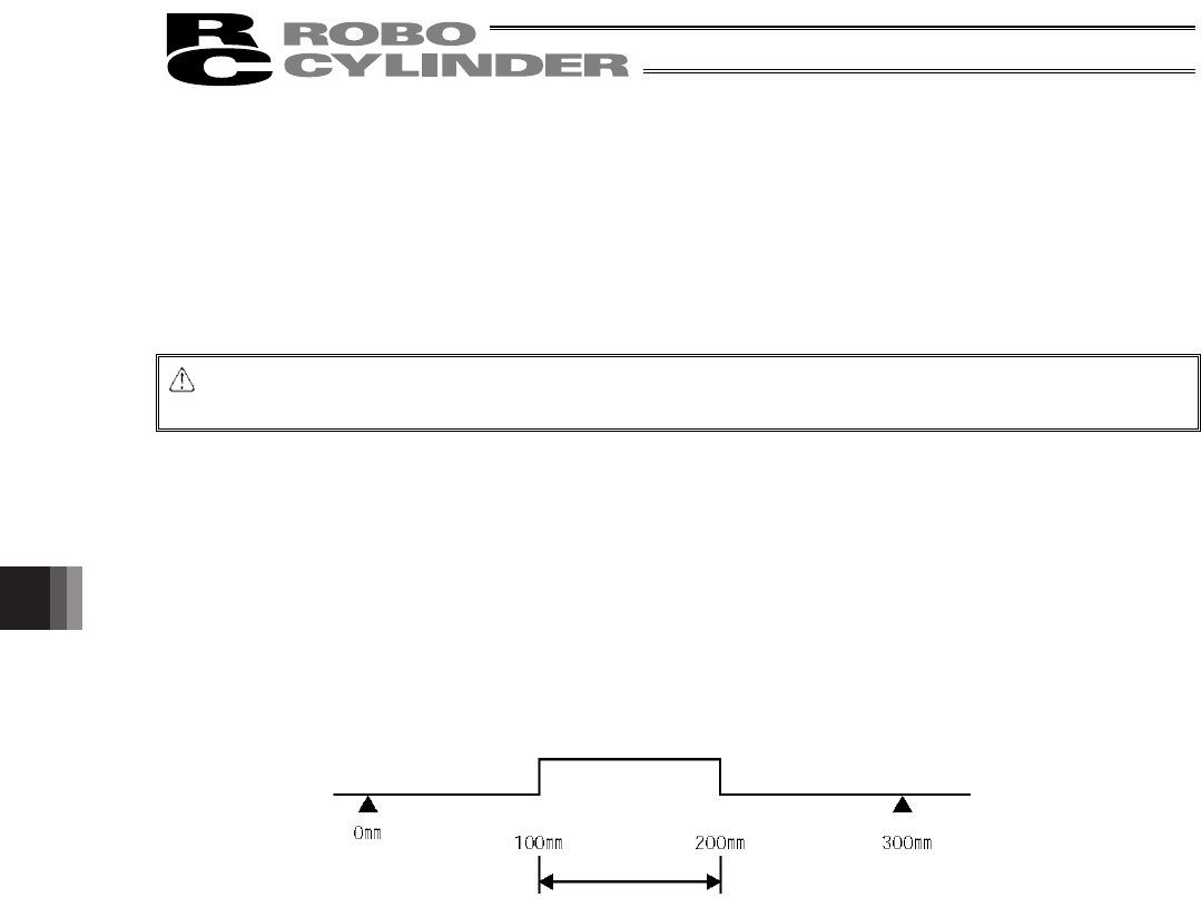
z Zone boundary
These parameters apply when the PIO pattern is 0 or 2, and set the zone in which the zone output signal (ZONE)
turns ON.
The zone output signal turns ON when the current position is inside the negative (–) boundary and positive (+)
boundary settings.
Set the + boundary in parameter No. 1 and – boundary in parameter No. 2.
The minimum setting unit is “0.01 [mm].”
Example) Turn ON the zone output signal in a range of 100 to 200 mm with the actuator having a 300-mm stroke
Parameter No. 1 (+) 200, parameter No. 2 (–) 100
(Home)
Zone in which ZONE turns ON