
Owner's manual


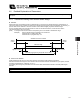


Table Of Contents
- Cover
- Please Read Before Use
- CAUTION
- CE Marking
- Table of Contents
- Safety Guide
- Caution in Handling
- 1. Overview
- 2. Installation
- 3. Wiring
- 3.1 Basic Structure
- 3.2 Configuration Using a SIO Converter
- 3.3 Configuration Using an Isolated PIO Terminal Block
- 3.4 Configuration Using Both SIO Converter and Isolated PIO Terminal Block
- 3.5 Specifications of I/O Signals
- 3.6 I/O Signals for PIO Pattern 1 [3 Points] (Air Cylinder)
- 3.7 I/O Signals for PIO Pattern 0 [8 Points]
- 3.8 I/O Signals for PIO Pattern 2 [16 Points] (Setting by Zone BoundaryParameters)
- 3.9 I/O Signals for PIO Pattern 3 [16 Points] (Setting in Zone Fields in thePosition Table)
- 3.10 Emergency-Stop Circuit
- 3.11 Extension Cable
- 4. Electrical Specifications
- 5. Data Entry
- 6. Operation in the “3 Points (Air Cylinder)” Mode
- 7. Operation in the “8 Points” and “16 Points” Modes
- 7.1 How to Start
- 7.2 Position Table and Parameter Settings Required for Operation
- 7.3 How to Execute Home Return
- 7.4 Home Return and Movement after Start (16 Points)
- 7.5 Positioning Mode (Back and Forth Movement between Two Points)
- 7.6 Push & Hold Mode
- 7.7 Speed Change during Movement
- 7.8 Operation at Different Acceleration and Deceleration Settings
- 7.9 Pause
- 7.10 Zone Signal
- 7.11 Incremental Moves
- 7.12 Notes on Incremental Mode
- 8. Parameter Settings
- 9. Troubleshooting
- 10. Maintenance and Inspection
- 11. Appendix
- Change History
129
7. Operation in the “8 Points” and “16 Points” Modes <Practical Operation>
120
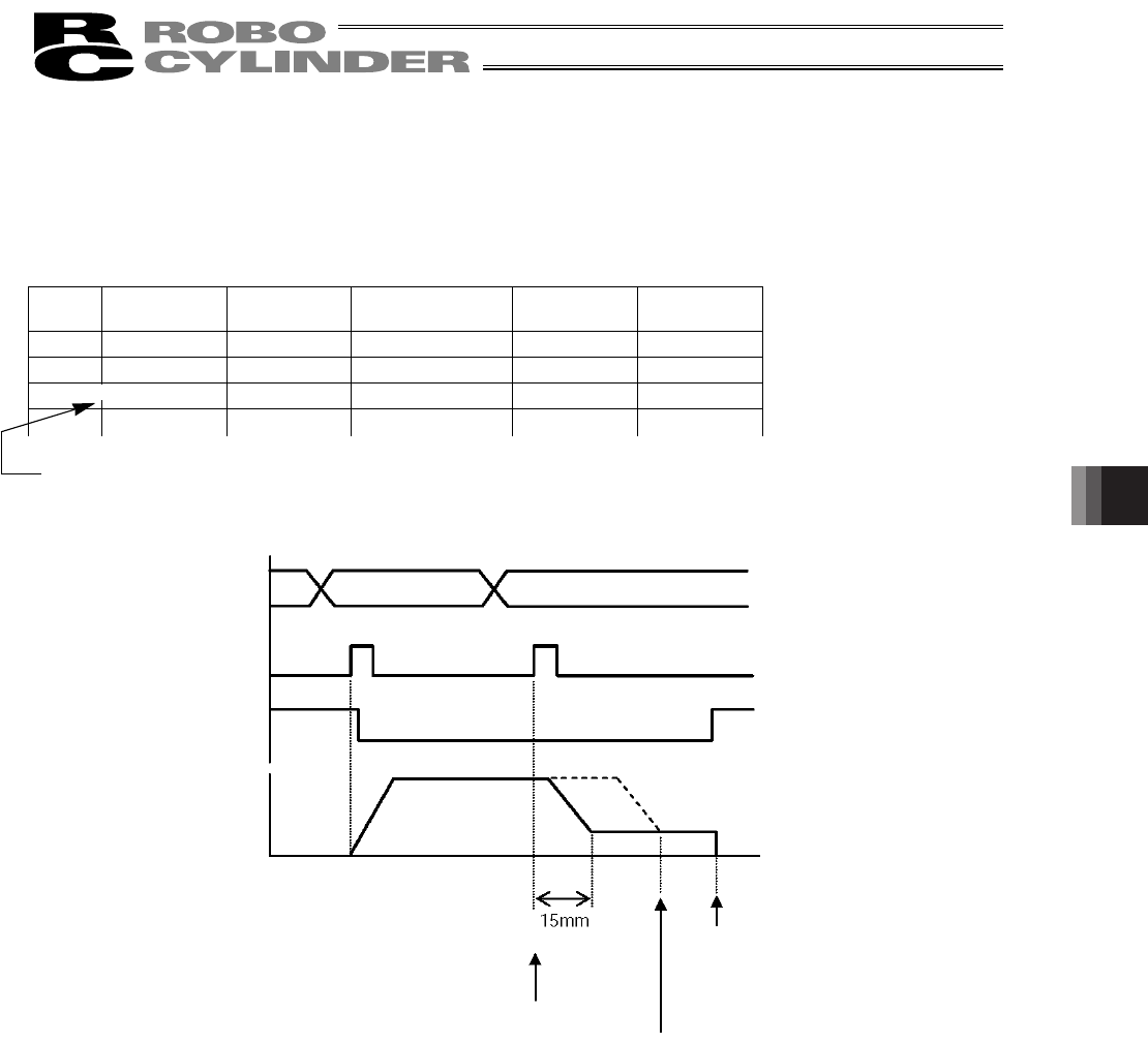
Command position
Start
Position complete
Actuator movement
Position 1 Position 2
Distance
Initial target position
200 mm
Position where the
push & hold
operation completes
Position where the start
signal input was received
Speed
z Moving in the push & hold mode to the position number set in the incremental mode
Example) If a start signal is input to initiate positioning to position 2 while the actuator is moving to position 1, the
actuator will move to a new target position, which is determined by adding the increment to the position at
which the start input was received.
Since the target position is indeterminable, never use this method.
Position-data table (Field(s) within thick line must be entered.)
No.
Position
[mm]
Speed
[mm/s]
Positioning band
[mm]
Push & hold
[%]
Incremental
0 * * * * *
1 200.00 100.00 30.00 50 0
2
15.00 20.00 60.00 50 1
x
x
x
Incremental moves
* On the teaching pendant screen, this sign indicates that
the position is specified in the incremental mode.
=