
Owner's manual


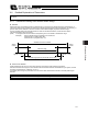


Table Of Contents
- Cover
- Please Read Before Use
- CAUTION
- CE Marking
- Table of Contents
- Safety Guide
- Caution in Handling
- 1. Overview
- 2. Installation
- 3. Wiring
- 3.1 Basic Structure
- 3.2 Configuration Using a SIO Converter
- 3.3 Configuration Using an Isolated PIO Terminal Block
- 3.4 Configuration Using Both SIO Converter and Isolated PIO Terminal Block
- 3.5 Specifications of I/O Signals
- 3.6 I/O Signals for PIO Pattern 1 [3 Points] (Air Cylinder)
- 3.7 I/O Signals for PIO Pattern 0 [8 Points]
- 3.8 I/O Signals for PIO Pattern 2 [16 Points] (Setting by Zone BoundaryParameters)
- 3.9 I/O Signals for PIO Pattern 3 [16 Points] (Setting in Zone Fields in thePosition Table)
- 3.10 Emergency-Stop Circuit
- 3.11 Extension Cable
- 4. Electrical Specifications
- 5. Data Entry
- 6. Operation in the “3 Points (Air Cylinder)” Mode
- 7. Operation in the “8 Points” and “16 Points” Modes
- 7.1 How to Start
- 7.2 Position Table and Parameter Settings Required for Operation
- 7.3 How to Execute Home Return
- 7.4 Home Return and Movement after Start (16 Points)
- 7.5 Positioning Mode (Back and Forth Movement between Two Points)
- 7.6 Push & Hold Mode
- 7.7 Speed Change during Movement
- 7.8 Operation at Different Acceleration and Deceleration Settings
- 7.9 Pause
- 7.10 Zone Signal
- 7.11 Incremental Moves
- 7.12 Notes on Incremental Mode
- 8. Parameter Settings
- 9. Troubleshooting
- 10. Maintenance and Inspection
- 11. Appendix
- Change History
128
7. Operation in the “8 Points” and “16 Points” Modes <Practical Operation>
119
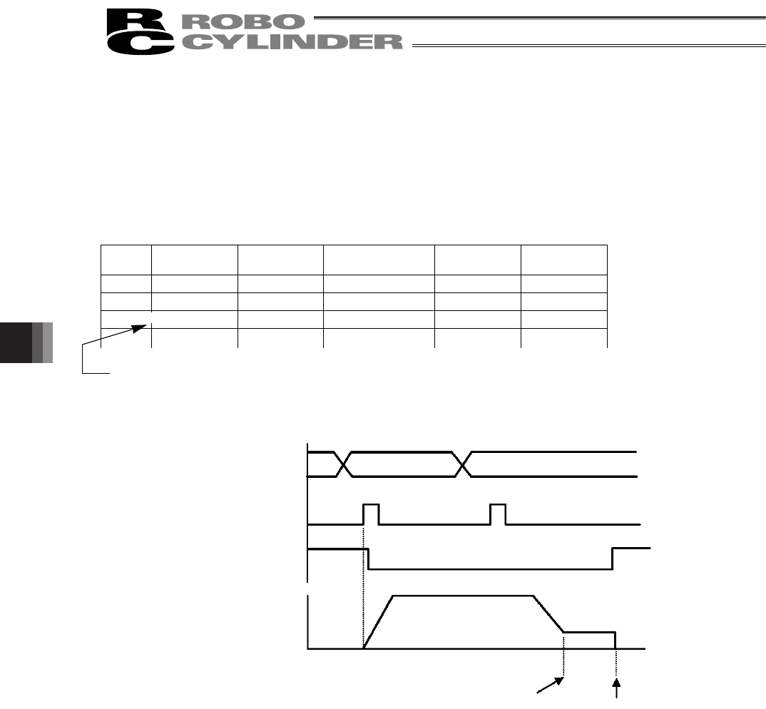
Command position
Start
Position complete
Actuator movement
Position 1 Position 2
Distance
Initial target position
200 mm
Stopped position
215 mm
Speed
(2) Push & hold mode
The following explains how the actuator will behave when a start signal is input after selecting/entering a position
number in the incremental mode while the actuator is moving in the push & hold mode.
z Positioning to the position number set in the incremental mode
Example) If a start signal is input to initiate positioning to position 2 while the actuator is moving to position 1, the
actuator will move to the position corresponding to the target position for position 1 plus the increment.
If the position table is set as shown below, the actuator will move to the 215-mm position.
Position-data table (Field(s) within thick line must be entered.)
No.
Position
[mm]
Speed
[mm/s]
Positioning band
[mm]
Push & hold
[%]
Incremental
0 * * * * *
1 200.00 100.00 30.00 50 6
2
15.00 20.00 0.10 0 1
x
x
x
Incremental moves
* On the teaching pendant screen, this sign indicates that
the position is specified in the incremental mode.
=