
Owner's manual

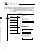


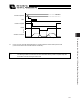
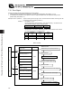

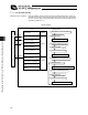
Table Of Contents
- Cover
- Please Read Before Use
- CAUTION
- CE Marking
- Table of Contents
- Safety Guide
- Caution in Handling
- 1. Overview
- 2. Installation
- 3. Wiring
- 3.1 Basic Structure
- 3.2 Configuration Using a SIO Converter
- 3.3 Configuration Using an Isolated PIO Terminal Block
- 3.4 Configuration Using Both SIO Converter and Isolated PIO Terminal Block
- 3.5 Specifications of I/O Signals
- 3.6 I/O Signals for PIO Pattern 1 [3 Points] (Air Cylinder)
- 3.7 I/O Signals for PIO Pattern 0 [8 Points]
- 3.8 I/O Signals for PIO Pattern 2 [16 Points] (Setting by Zone BoundaryParameters)
- 3.9 I/O Signals for PIO Pattern 3 [16 Points] (Setting in Zone Fields in thePosition Table)
- 3.10 Emergency-Stop Circuit
- 3.11 Extension Cable
- 4. Electrical Specifications
- 5. Data Entry
- 6. Operation in the “3 Points (Air Cylinder)” Mode
- 7. Operation in the “8 Points” and “16 Points” Modes
- 7.1 How to Start
- 7.2 Position Table and Parameter Settings Required for Operation
- 7.3 How to Execute Home Return
- 7.4 Home Return and Movement after Start (16 Points)
- 7.5 Positioning Mode (Back and Forth Movement between Two Points)
- 7.6 Push & Hold Mode
- 7.7 Speed Change during Movement
- 7.8 Operation at Different Acceleration and Deceleration Settings
- 7.9 Pause
- 7.10 Zone Signal
- 7.11 Incremental Moves
- 7.12 Notes on Incremental Mode
- 8. Parameter Settings
- 9. Troubleshooting
- 10. Maintenance and Inspection
- 11. Appendix
- Change History
124
7. Operation in the “8 Points” and “16 Points” Modes <Practical Operation>
115
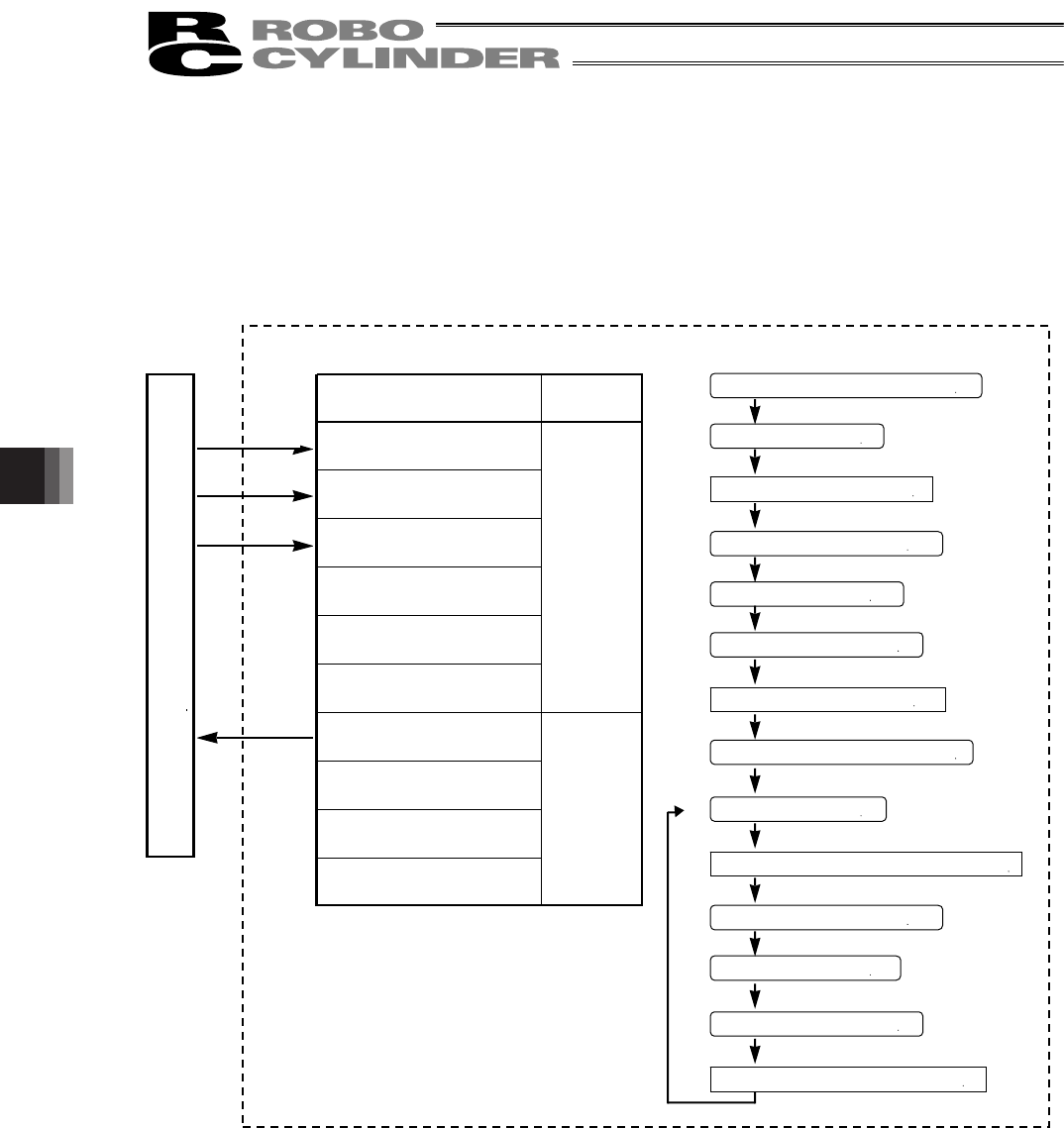
7.11 Incremental Moves
Example of use in operation) Move the actuator from the home to the 30-mm position (position No. 1) set in the
absolute mode, and then move the actuator further through continuous incremental
moves at a 10-mm pitch until the final position of 200 mm is reached. (Pitch feed is
specified by position No. 2.)
ERC2 controller
P
L
C
[1]
[6]
[10] [8] [5] [3]
PIO
Signal name
Start
Command position 1
Command position 2
Command position 4
Command position 8
*Pause
Position complete
Home return completion
Zone
*Alarm
Category
Input
Output
[9] [7] [4] [2]
Reference flow
Select/enter command position 1.
Start input ON
Movement to position 1 starts.
Position complete output OFF
Start input OFF
Position complete output ON
Select/enter command position 2.
Start input ON
Position complete output OFF
Start input OFF
Movement to the +10 mm position completes.
Position complete output ON
Movement to position 1 completes.
Movement to +10 mm from the current position starts.
[1]
[2]
[3]
[4]
[5]
[6]
[7]
[8]
[9]
[10]