
Owner's manual
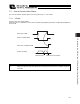


Table Of Contents
- Cover
- Please Read Before Use
- CAUTION
- CE Marking
- Table of Contents
- Safety Guide
- Caution in Handling
- 1. Overview
- 2. Installation
- 3. Wiring
- 3.1 Basic Structure
- 3.2 Configuration Using a SIO Converter
- 3.3 Configuration Using an Isolated PIO Terminal Block
- 3.4 Configuration Using Both SIO Converter and Isolated PIO Terminal Block
- 3.5 Specifications of I/O Signals
- 3.6 I/O Signals for PIO Pattern 1 [3 Points] (Air Cylinder)
- 3.7 I/O Signals for PIO Pattern 0 [8 Points]
- 3.8 I/O Signals for PIO Pattern 2 [16 Points] (Setting by Zone BoundaryParameters)
- 3.9 I/O Signals for PIO Pattern 3 [16 Points] (Setting in Zone Fields in thePosition Table)
- 3.10 Emergency-Stop Circuit
- 3.11 Extension Cable
- 4. Electrical Specifications
- 5. Data Entry
- 6. Operation in the “3 Points (Air Cylinder)” Mode
- 7. Operation in the “8 Points” and “16 Points” Modes
- 7.1 How to Start
- 7.2 Position Table and Parameter Settings Required for Operation
- 7.3 How to Execute Home Return
- 7.4 Home Return and Movement after Start (16 Points)
- 7.5 Positioning Mode (Back and Forth Movement between Two Points)
- 7.6 Push & Hold Mode
- 7.7 Speed Change during Movement
- 7.8 Operation at Different Acceleration and Deceleration Settings
- 7.9 Pause
- 7.10 Zone Signal
- 7.11 Incremental Moves
- 7.12 Notes on Incremental Mode
- 8. Parameter Settings
- 9. Troubleshooting
- 10. Maintenance and Inspection
- 11. Appendix
- Change History

116
7. Operation in the “8 Points” and “16 Points” Modes <Practical Operation>
107
7.7 Speed Change during Movement
Example of use in operation) The actuator speed is reduced at a certain point during movement.
The position 150 mm from the home is set as position 1, and the position 200 mm
from the home is set as position 2. The actuator is initially located between the home
and position 1. The actuator is moved to position 2 being the target position, at a
travel speed of 200 mm/sec to position 1 and that of 100 mm/sec from position 1 to
position 2.
Method) In this example, the actuator is caused to move to position 1 and to position 2
successively. Before the actuator is stopped at position 1, command position 2 must
be selected/entered and the start signal must be input. To do this, set a wide
positioning band at position 1 and cause the start signal for movement to position 2 to
be input immediately after the completion signal for movement to position 1 is output.
(Command position 2 should be entered while the actuator is moving to position 1.)
ERC2 controller
[9] [7] [4] [2]
[1]
[5]
Signal name
Start
Command position 1
Command position 2
Command position 4
Command position 8
*Pause
Position complete
Home return completion
Zone
*Alarm
Category
Input
Output
[10] [8] [6] [3]
P
L
C
PIO
Reference flow
Select/enter command position 1.
Start input ON
Movement to position 1 starts at 200 mm/sec.
Position complete output OFF
Start input OFF
Select/enter command position 2.
Start input ON
Position complete output OFF
Start input OFF
Movement to position 2 completes.
Position complete output turns
ON 10 mm before position 1.
Movement to position 2 starts at 100 mm/sec.
Position complete output turns
ON 0.1 mm before position 2.
[1]
[2]
[3]
[4]
[5]
[6]
[7]
[8]
[9]
[10]