
Owner's manual
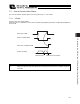


Table Of Contents
- Cover
- Please Read Before Use
- CAUTION
- CE Marking
- Table of Contents
- Safety Guide
- Caution in Handling
- 1. Overview
- 2. Installation
- 3. Wiring
- 3.1 Basic Structure
- 3.2 Configuration Using a SIO Converter
- 3.3 Configuration Using an Isolated PIO Terminal Block
- 3.4 Configuration Using Both SIO Converter and Isolated PIO Terminal Block
- 3.5 Specifications of I/O Signals
- 3.6 I/O Signals for PIO Pattern 1 [3 Points] (Air Cylinder)
- 3.7 I/O Signals for PIO Pattern 0 [8 Points]
- 3.8 I/O Signals for PIO Pattern 2 [16 Points] (Setting by Zone BoundaryParameters)
- 3.9 I/O Signals for PIO Pattern 3 [16 Points] (Setting in Zone Fields in thePosition Table)
- 3.10 Emergency-Stop Circuit
- 3.11 Extension Cable
- 4. Electrical Specifications
- 5. Data Entry
- 6. Operation in the “3 Points (Air Cylinder)” Mode
- 7. Operation in the “8 Points” and “16 Points” Modes
- 7.1 How to Start
- 7.2 Position Table and Parameter Settings Required for Operation
- 7.3 How to Execute Home Return
- 7.4 Home Return and Movement after Start (16 Points)
- 7.5 Positioning Mode (Back and Forth Movement between Two Points)
- 7.6 Push & Hold Mode
- 7.7 Speed Change during Movement
- 7.8 Operation at Different Acceleration and Deceleration Settings
- 7.9 Pause
- 7.10 Zone Signal
- 7.11 Incremental Moves
- 7.12 Notes on Incremental Mode
- 8. Parameter Settings
- 9. Troubleshooting
- 10. Maintenance and Inspection
- 11. Appendix
- Change History
114
7. Operation in the “8 Points” and “16 Points” Modes <Practical Operation>
105
Position-data table (Field(s) within thick line must be entered.)
No.
Position
[mm]
Speed
[mm/s]
Acceleration
[G]
Deceleration
[G]
Push
[%]
Positioning band
[mm]
0 * * * *
*
*
1 280.00 200.00 0.30 0.30 50 15.00
2 40.00 100.00 0.30 0.30
0
0.10
x
x
x
T1: 6 msec or more; time after selecting/entering a command position until the start input turns ON
(The scan time of the host controller must be considered.)
Each command position must be input after the position complete output has turned ON for the movement to the
previous position.
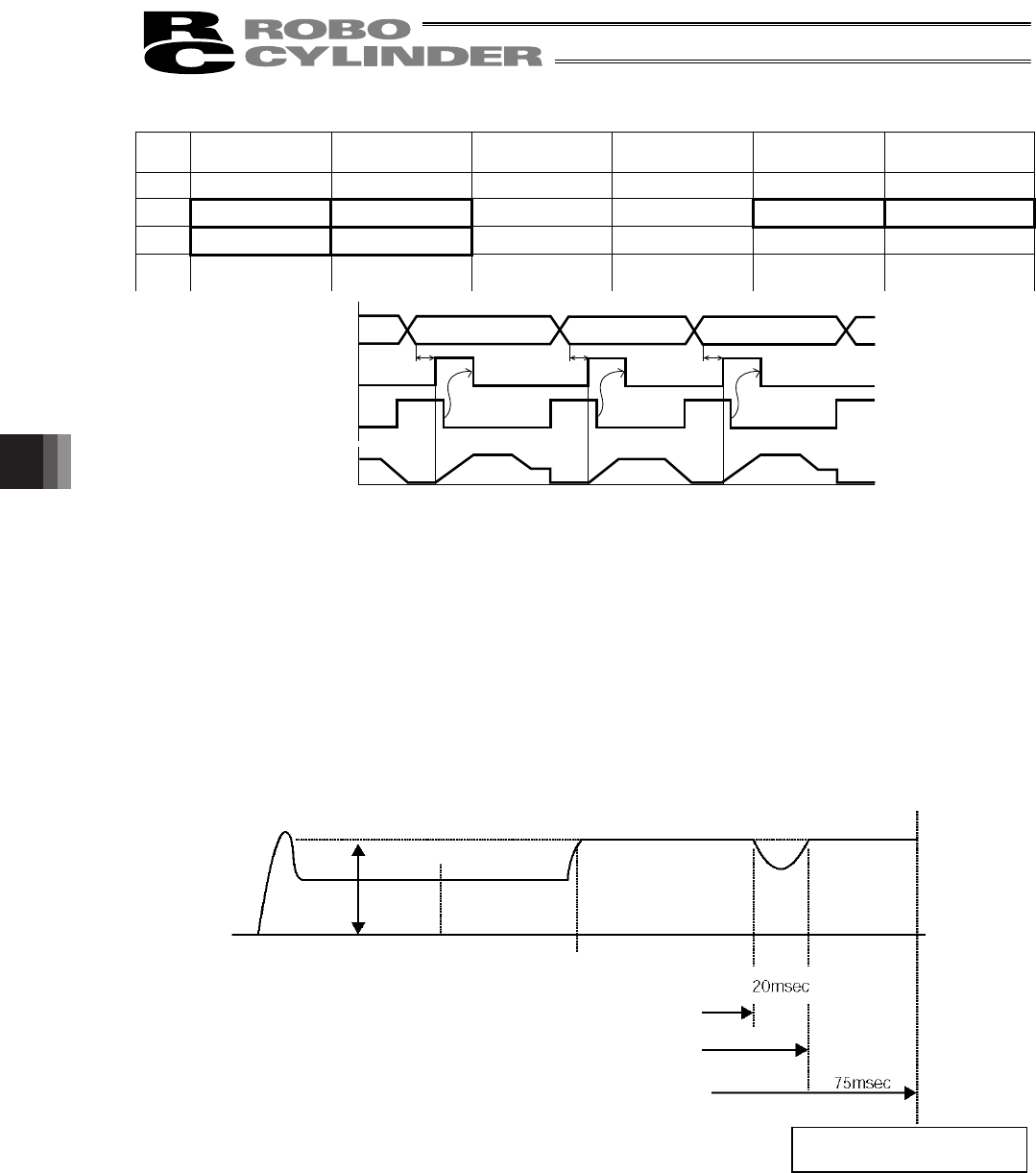
z Conditions for determining completion of push & hold operation
Push & hold operation is deemed to have completed upon elapse of the time set by parameter No. 6 (Push
completion judgment time) after the motor current reached the current-limiting value set in the “Push” field of the
position table.
Set an appropriate value by considering the material and shape of the work part, and so on.
The minimum setting unit is “1 msec,” while the maximum value is “9999 msec.” The factory setting is “255 msec.”
(Note) The chart below explains how completion of push & hold operation is determined if the work part shifted
during the judgment and the current has changed as a result, based on a judgment time of 255 msec.
If the motor current remains at or above the push current for 200 msec and then drops below this level for 20 msec,
the count will decrease by 20. When the push current is reached again thereafter, counting will start from 180. If the
motor current remains at or above the push current for 75 msec, the count will increase to 255 and thus push & hold
operation will be deemed to have completed.
In total, 295 msec was required for the judgment.
Position 1
Position 2
Position 1
Command position
Start
Position complete
Actuator movement
T
1
T
1
T
1
Completion of push & hold operation Completion of push & hold operation
Push current
Starting position Target position Counting starts.
The count increases to 200.
The count decreases to 180.
The count increases to 255.
Push & hold operation is
deemed to have completed.
Speed