
Owner's manual


Table Of Contents
- Cover
- Please Read Before Use
- CAUTION
- CE Marking
- Table of Contents
- Safety Guide
- Caution in Handling
- 1. Overview
- 2. Installation
- 3. Wiring
- 3.1 Basic Structure
- 3.2 Configuration Using a SIO Converter
- 3.3 Configuration Using an Isolated PIO Terminal Block
- 3.4 Configuration Using Both SIO Converter and Isolated PIO Terminal Block
- 3.5 Specifications of I/O Signals
- 3.6 I/O Signals for PIO Pattern 1 [3 Points] (Air Cylinder)
- 3.7 I/O Signals for PIO Pattern 0 [8 Points]
- 3.8 I/O Signals for PIO Pattern 2 [16 Points] (Setting by Zone BoundaryParameters)
- 3.9 I/O Signals for PIO Pattern 3 [16 Points] (Setting in Zone Fields in thePosition Table)
- 3.10 Emergency-Stop Circuit
- 3.11 Extension Cable
- 4. Electrical Specifications
- 5. Data Entry
- 6. Operation in the “3 Points (Air Cylinder)” Mode
- 7. Operation in the “8 Points” and “16 Points” Modes
- 7.1 How to Start
- 7.2 Position Table and Parameter Settings Required for Operation
- 7.3 How to Execute Home Return
- 7.4 Home Return and Movement after Start (16 Points)
- 7.5 Positioning Mode (Back and Forth Movement between Two Points)
- 7.6 Push & Hold Mode
- 7.7 Speed Change during Movement
- 7.8 Operation at Different Acceleration and Deceleration Settings
- 7.9 Pause
- 7.10 Zone Signal
- 7.11 Incremental Moves
- 7.12 Notes on Incremental Mode
- 8. Parameter Settings
- 9. Troubleshooting
- 10. Maintenance and Inspection
- 11. Appendix
- Change History
102
6. Operation in the “3 Points (Air Cylinder)” Mode <Practical Operation>
93
z Handling of the pause (*STP) signal
This signal is a Contact B signal, meaning that it must remain ON while the actuator is moving.
If the pause signal turns OFF while the actuator is moving, the actuator will decelerate to a stop.
The actuator will start moving when the signal turns ON again.
Use this signal as an interlock that actuates when an operator entry prohibition sensor or contact prevention
sensor is activated.
If the pause signal is not to be used, set parameter No. 15 (Pause input disable selection) to “1,” and the actuator
will move even when this signal is OFF.
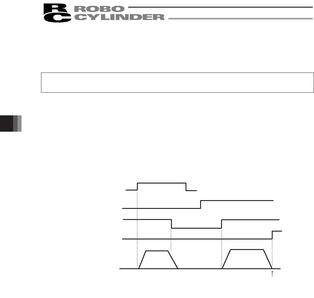
(Note) When the “edge mode” is selected as the movement command type, you may want to change the target
position while the actuator is stopped with this signal turned OFF. In this case, input a movement
command specifying the new target position, and then turn ON this signal.
(Example) If the pause signal is turned OFF while the actuator is moving following the input of an
intermediate point move command, the accelerator will decelerate to a stop.
o Turn OFF the intermediate point move signal, and then turn ON the front end move signal.
o When the pause signal is turned ON again, the controller will recognize the front end as
the new target position.
Intermediate point move
Front end move
Pause
Front end complete
Actuator movement
The front end becomes the
target position.
Stopped