
Owner's manual


Table Of Contents
- Cover
- Please Read Before Use
- CAUTION
- CE Marking
- Table of Contents
- Safety Guide
- Caution in Handling
- 1. Overview
- 2. Installation
- 3. Wiring
- 3.1 Basic Structure
- 3.2 Configuration Using a SIO Converter
- 3.3 Configuration Using an Isolated PIO Terminal Block
- 3.4 Configuration Using Both SIO Converter and Isolated PIO Terminal Block
- 3.5 Specifications of I/O Signals
- 3.6 I/O Signals for PIO Pattern 1 [3 Points] (Air Cylinder)
- 3.7 I/O Signals for PIO Pattern 0 [8 Points]
- 3.8 I/O Signals for PIO Pattern 2 [16 Points] (Setting by Zone BoundaryParameters)
- 3.9 I/O Signals for PIO Pattern 3 [16 Points] (Setting in Zone Fields in thePosition Table)
- 3.10 Emergency-Stop Circuit
- 3.11 Extension Cable
- 4. Electrical Specifications
- 5. Data Entry
- 6. Operation in the “3 Points (Air Cylinder)” Mode
- 7. Operation in the “8 Points” and “16 Points” Modes
- 7.1 How to Start
- 7.2 Position Table and Parameter Settings Required for Operation
- 7.3 How to Execute Home Return
- 7.4 Home Return and Movement after Start (16 Points)
- 7.5 Positioning Mode (Back and Forth Movement between Two Points)
- 7.6 Push & Hold Mode
- 7.7 Speed Change during Movement
- 7.8 Operation at Different Acceleration and Deceleration Settings
- 7.9 Pause
- 7.10 Zone Signal
- 7.11 Incremental Moves
- 7.12 Notes on Incremental Mode
- 8. Parameter Settings
- 9. Troubleshooting
- 10. Maintenance and Inspection
- 11. Appendix
- Change History
96
6. Operation in the “3 Points (Air Cylinder)” Mode <Practical Operation>
87
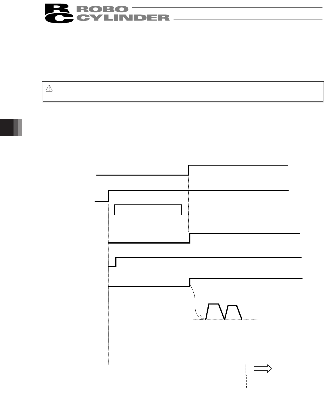
If the actuator does not perform home return, confirm that the *pause signal is ON, the motor-drive power supply
is receiving power, and no error messages are displayed, among others.
(10) Set the target position, speed, acceleration/deceleration, positioning band and other data in the position table.
For details on how to set data in the position table, refer to the operation manual for the teaching pendant or PC
software, whichever is applicable.
Now, you can operate the actuator automatically via control from the PLC.
Caution: Move the actuator to the target position after confirming that the *ALM output is ON and the motor
drive power is supplied.
Timing chart at start
Motor-drive power
supply
Input of 24-VDC
power supply
LED lamp
Alarm output (*ALM)
Pause input (*STP)
Home return
Cut off
Supplied
Initial parameter setting
Orange light turns on for 2
seconds, and then turns off.
Green
Pause is released.
Movement starts
Mechanical end
Home position
Create a position table
via teaching pendant or
PC operation.