
Owner's manual
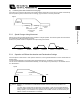


Table Of Contents
- Cover
- Please Read Before Use
- CAUTION
- CE Marking
- Table of Contents
- Safety Guide
- Caution in Handling
- 1. Overview
- 2. Installation
- 3. Wiring
- 3.1 Basic Structure
- 3.2 Configuration Using a SIO Converter
- 3.3 Configuration Using an Isolated PIO Terminal Block
- 3.4 Configuration Using Both SIO Converter and Isolated PIO Terminal Block
- 3.5 Specifications of I/O Signals
- 3.6 I/O Signals for PIO Pattern 1 [3 Points] (Air Cylinder)
- 3.7 I/O Signals for PIO Pattern 0 [8 Points]
- 3.8 I/O Signals for PIO Pattern 2 [16 Points] (Setting by Zone BoundaryParameters)
- 3.9 I/O Signals for PIO Pattern 3 [16 Points] (Setting in Zone Fields in thePosition Table)
- 3.10 Emergency-Stop Circuit
- 3.11 Extension Cable
- 4. Electrical Specifications
- 5. Data Entry
- 6. Operation in the “3 Points (Air Cylinder)” Mode
- 7. Operation in the “8 Points” and “16 Points” Modes
- 7.1 How to Start
- 7.2 Position Table and Parameter Settings Required for Operation
- 7.3 How to Execute Home Return
- 7.4 Home Return and Movement after Start (16 Points)
- 7.5 Positioning Mode (Back and Forth Movement between Two Points)
- 7.6 Push & Hold Mode
- 7.7 Speed Change during Movement
- 7.8 Operation at Different Acceleration and Deceleration Settings
- 7.9 Pause
- 7.10 Zone Signal
- 7.11 Incremental Moves
- 7.12 Notes on Incremental Mode
- 8. Parameter Settings
- 9. Troubleshooting
- 10. Maintenance and Inspection
- 11. Appendix
- Change History

95
6. Operation in the “3 Points (Air Cylinder)” Mode <Practical Operation>
86
6.2 How to Start
(1) Confirm that the connector end (CN1) of the extension cable is firmly plugged into the connector on the actuator
cable.
(2) Connect the PLC and the parallel I/O.
(3) If the actuator has brake, set the brake release switch to OFF.
(4) Supply 24 VDC to the control power supply.
Cut off the motor-drive power supply (actuate an emergency stop) beforehand.
(5) Confirm that the slider or rod is not contacting the mechanical end. If the slider or rod is contacting the
mechanical end, or when the slider or rod is positioned between the mechanical end and home, move the
slider/rod away from the home position toward the direction opposite to the mechanical end.
If the actuator is equipped with a brake, move the slider/rod after releasing the brake by turning on the brake
release switch. At this time, pay attention to prevent the load from falling by its dead weight and protect your
hand, robot, and the work part from injuries/damages.
If the screw lead is too short and the actuator cannot be moved by hand, change the setting of parameter No. 28,
“Direction of excited-phase signal detection” to the direction opposite to the mechanical end.
Warning: Turning on the servo while the slider or rod is still contacting the mechanical end may disable
accurate detection of the excited phase, resulting in malfunction or excitation detection error.
(6) Connect a PC or teaching pendant and set the minimum parameters required.
x If the pause input is not used, set parameter No. 15 “Pause input disable selection” to “1.”
x Set parameter No. 25 “PIO pattern selection” to “1” (this setting is required).
x If you want to use the movement command input based on the “edge mode,” set parameter No. 27 to “1.”
For details, refer to 8, “Parameter Settings.”
(7) Cancel the emergency stop so that the motor drive power will be supplied.
The controller servo will be turned on and a green LED lamp will illuminate on the motor cover.
(8) If the pause signal (*STP) is enabled, turn the signal ON from the PLC.
A red LED lamp indicates an alarm. Remove the cause of the alarm.
For details, refer to 9, “Troubleshooting.”
(9) Perform home return.
z Overview of operation on the teaching pendant
x On the RCM-T, select the Edit/Teach screen, bring the cursor to *Home in the sub-display area, and then
press the ENTER key.
x On the RCM-E, select the Teach/Play screen, scroll the pages until *Home Return is shown, and then press
the ENTER key.
z Overview of operation in the PC software
In the main window, select the applicable position data, and then click Home.
For details of each operation, refer to the operation manual for the applicable teaching pendant or PC
software.