
Owner's manual
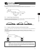


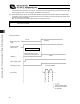
Table Of Contents
- Cover
- Please Read Before Use
- CAUTION
- CE Marking
- Table of Contents
- Safety Guide
- Caution in Handling
- 1. Overview
- 2. Installation
- 3. Wiring
- 3.1 Basic Structure
- 3.2 Configuration Using a SIO Converter
- 3.3 Configuration Using an Isolated PIO Terminal Block
- 3.4 Configuration Using Both SIO Converter and Isolated PIO Terminal Block
- 3.5 Specifications of I/O Signals
- 3.6 I/O Signals for PIO Pattern 1 [3 Points] (Air Cylinder)
- 3.7 I/O Signals for PIO Pattern 0 [8 Points]
- 3.8 I/O Signals for PIO Pattern 2 [16 Points] (Setting by Zone BoundaryParameters)
- 3.9 I/O Signals for PIO Pattern 3 [16 Points] (Setting in Zone Fields in thePosition Table)
- 3.10 Emergency-Stop Circuit
- 3.11 Extension Cable
- 4. Electrical Specifications
- 5. Data Entry
- 6. Operation in the “3 Points (Air Cylinder)” Mode
- 7. Operation in the “8 Points” and “16 Points” Modes
- 7.1 How to Start
- 7.2 Position Table and Parameter Settings Required for Operation
- 7.3 How to Execute Home Return
- 7.4 Home Return and Movement after Start (16 Points)
- 7.5 Positioning Mode (Back and Forth Movement between Two Points)
- 7.6 Push & Hold Mode
- 7.7 Speed Change during Movement
- 7.8 Operation at Different Acceleration and Deceleration Settings
- 7.9 Pause
- 7.10 Zone Signal
- 7.11 Incremental Moves
- 7.12 Notes on Incremental Mode
- 8. Parameter Settings
- 9. Troubleshooting
- 10. Maintenance and Inspection
- 11. Appendix
- Change History
94
6. Operation in the “3 Points (Air Cylinder)” Mode <Practical Operation>
85
The relationships of movement command inputs/position complete outputs and corresponding position numbers are
shown below.
For easier identification, each input/output signal has a name similar to the naming convention used with air cylinders.
However, note that the target position is determined by the value set in the [Target position] field under each position
number. Therefore, changing the magnitude correlation of the settings in Nos. 0 to 2 will change the meanings of the
corresponding input/output signals.
Accordingly, the settings in the respective position numbers should match the semantic meanings of the
corresponding signal names used in this operation manual, unless doing so will pose a problem.
Input signal Output signal Target position
Rear end move (ST0) Rear end complete (PE0)
Setting in the [Target position] field under
position No. 0 Example: 5 mm
Front end move (ST1) Front end complete (PE1)
Setting in the [Target position] field under
position No. 1 Example: 390 mm
Intermediate point move (ST2) Intermediate point complete (PE2)
Setting in the [Target position] field under
position No. 2 Example: 200 mm
z Positioning relationships on the Robo Cylinder
This example assumes the use of a slider type actuator with a 400 mm stroke.
[Motor side] [Counter-motor side]
z Position table (Field(s) within thick line must be entered.)
No.
Position
[mm]
Speed
[mm/s]
Acceleration
[G]
Deceleration
[G]
Push
[%]
Positioning band
[mm]
0 5.00 500.00 0.30 0.30 0 0.10
1 390.00 500.00 0.30 0.30 0 0.10
2 200.00 500.00 0.30 0.30 0 0.10
Home (0 mm)
Rear end complete (5 mm)
Front end complete (390 mm)
Intermediate point complete (200 mm)