
Owner's manual
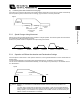


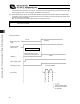
Table Of Contents
- Cover
- Please Read Before Use
- CAUTION
- CE Marking
- Table of Contents
- Safety Guide
- Caution in Handling
- 1. Overview
- 2. Installation
- 3. Wiring
- 3.1 Basic Structure
- 3.2 Configuration Using a SIO Converter
- 3.3 Configuration Using an Isolated PIO Terminal Block
- 3.4 Configuration Using Both SIO Converter and Isolated PIO Terminal Block
- 3.5 Specifications of I/O Signals
- 3.6 I/O Signals for PIO Pattern 1 [3 Points] (Air Cylinder)
- 3.7 I/O Signals for PIO Pattern 0 [8 Points]
- 3.8 I/O Signals for PIO Pattern 2 [16 Points] (Setting by Zone BoundaryParameters)
- 3.9 I/O Signals for PIO Pattern 3 [16 Points] (Setting in Zone Fields in thePosition Table)
- 3.10 Emergency-Stop Circuit
- 3.11 Extension Cable
- 4. Electrical Specifications
- 5. Data Entry
- 6. Operation in the “3 Points (Air Cylinder)” Mode
- 7. Operation in the “8 Points” and “16 Points” Modes
- 7.1 How to Start
- 7.2 Position Table and Parameter Settings Required for Operation
- 7.3 How to Execute Home Return
- 7.4 Home Return and Movement after Start (16 Points)
- 7.5 Positioning Mode (Back and Forth Movement between Two Points)
- 7.6 Push & Hold Mode
- 7.7 Speed Change during Movement
- 7.8 Operation at Different Acceleration and Deceleration Settings
- 7.9 Pause
- 7.10 Zone Signal
- 7.11 Incremental Moves
- 7.12 Notes on Incremental Mode
- 8. Parameter Settings
- 9. Troubleshooting
- 10. Maintenance and Inspection
- 11. Appendix
- Change History
88
5. Data Entry <Basic>
79
5.2.5 Pause
The actuator can be paused during movement using an external input signal (*pause).
The pause signal uses the contact B logic (always ON) to ensure safety.
Turning OFF the *pause input will cause the actuator to decelerate to a stop, while turning it ON will allow the actuator
to complete the remaining operation.
(Note) The deceleration becomes the value set in the “Deceleration” field of the position table for the position
number corresponding to the current positioning operation.
5.2.6 Zone Signal Output
The zone signal is output when the actuator enters the specified zone during movement. Accordingly, this signal can
be used for the following purposes:
[1] As a trigger signal for peripheral equipment to reduce the tact time
[2] To prevent contact with peripheral equipment
[3] As a “simple ruler” in push & hold operation
The zone in which the signal turns ON varies depending on the PIO pattern
PIO pattern = 0 (8 points) or 2 (16 points: setting by zone boundary parameters)
The zone in which the zone signal turns ON is set by parameters.
Parameter No. 1 = Zone boundary+, parameter No. 2 = Zone boundary–
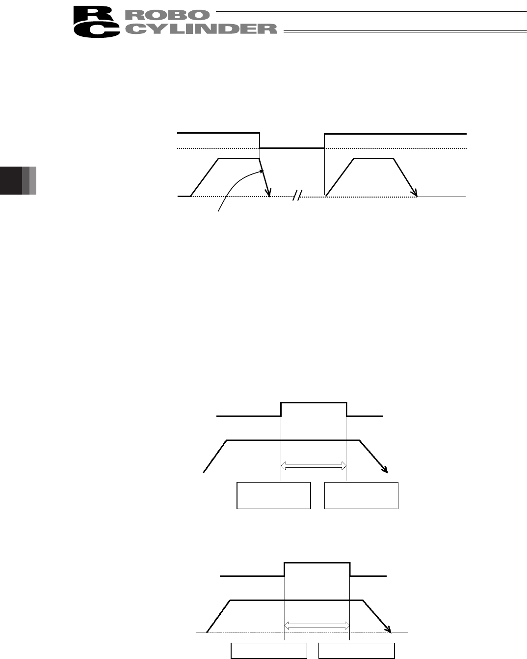
PIO pattern = 3 (16 points: setting in zone fields in the position table)
The zone in which the zone signal turns ON is set by the “Zone–” and “Zone+” fields of the position table.
ON ON
OFF
*Pause signal
Actuator operation
Target position
Actuator operation
Zone output (ZONE)
Home
Setting of
parameter No. 2
Setting of
parameter No. 1
+ direction
Actuator operation
Zone output (PZONE)
Home
Setting of “Zone–” Setting of “Zone+”
+ direction