
Owner's manual


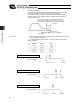


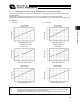


Table Of Contents
- Cover
- Please Read Before Use
- CAUTION
- CE Marking
- Table of Contents
- Safety Guide
- Caution in Handling
- 1. Overview
- 2. Installation
- 3. Wiring
- 3.1 Basic Structure
- 3.2 Configuration Using a SIO Converter
- 3.3 Configuration Using an Isolated PIO Terminal Block
- 3.4 Configuration Using Both SIO Converter and Isolated PIO Terminal Block
- 3.5 Specifications of I/O Signals
- 3.6 I/O Signals for PIO Pattern 1 [3 Points] (Air Cylinder)
- 3.7 I/O Signals for PIO Pattern 0 [8 Points]
- 3.8 I/O Signals for PIO Pattern 2 [16 Points] (Setting by Zone BoundaryParameters)
- 3.9 I/O Signals for PIO Pattern 3 [16 Points] (Setting in Zone Fields in thePosition Table)
- 3.10 Emergency-Stop Circuit
- 3.11 Extension Cable
- 4. Electrical Specifications
- 5. Data Entry
- 6. Operation in the “3 Points (Air Cylinder)” Mode
- 7. Operation in the “8 Points” and “16 Points” Modes
- 7.1 How to Start
- 7.2 Position Table and Parameter Settings Required for Operation
- 7.3 How to Execute Home Return
- 7.4 Home Return and Movement after Start (16 Points)
- 7.5 Positioning Mode (Back and Forth Movement between Two Points)
- 7.6 Push & Hold Mode
- 7.7 Speed Change during Movement
- 7.8 Operation at Different Acceleration and Deceleration Settings
- 7.9 Pause
- 7.10 Zone Signal
- 7.11 Incremental Moves
- 7.12 Notes on Incremental Mode
- 8. Parameter Settings
- 9. Troubleshooting
- 10. Maintenance and Inspection
- 11. Appendix
- Change History

86
5. Data Entry <Basic>
77
(2) Work part was not contacted (missed)
The position complete signal will not turn ON if the actuator does not yet contact the work part after moving the
distance set in the “Positioning band” field.
Therefore, include a timeout check process in the sequence circuit on the PLC side.
(3) Work part moves during push & hold operation
[1] The work part moves in the pushed direction
If the work part moves in the pushed direction after the push & hold operation has completed, the actuator will
chase the work part within the positioning band.
If the current drops below the current-limiting value set in the “Push” field of the position table, the position
complete signal will turn OFF. The signal will turn ON when the current rises to or above the current-limiting value
again.
[2] The work part moves in the opposite direction
(The actuator is pushed back by a strong reactive force of the work part.)
If the actuator is pushed back after the push & hold operation has completed because the actuator thrust is
smaller than the reactive force of the work part, the actuator will be pushed back all the way until its thrust
balances out with the reactive force of the work part.
The position complete signal remains ON.
(Note) If the actuator is pushed back to the target position, an alarm will occur.
Speed
If the actuator does not contact
the load, the position complete
signal does not turn ON.
Moving distance
Positioning band
(Maximum push distance)
Target position
Speed
Moving distance
Positioning band
(Maximum push distance)
Target position
Position where the push
& hold operation is
determined complete
If the load moves forward, the
actuator chases the load within
the positioning band.
Speed
Moving distance
Positioning band
(Maximum push distance)
Target position
Position where the push
& hold operation is
determined complete