
Manual


58
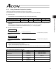
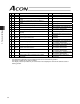
5. Parameter Settings
No. Type Symbol Name Unit Factory default
55 b PLPF
Primary filter time constant for position command
msec 0
57 b TQLM Torque limit % 70
58 c SDCR
Clear deviation at servo off/alarm stop [0: Disable / 1:
Enable]
- 1 [Enable]
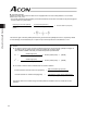
59 b FSTP
Monitor error while limiting torque [0: Disable / 1:
Enable]
- 1 [Enable]
60 c DCLR Deviation-counter clear input [0: Enable / 1: Disable] - 0 [Enable]
61 c TL Torque-limit command input [0: Enable / 1: Disable] - 0 [Enable]
62 b CPR Pulse count direction [0: Forward / 1: Reverse] -
Set individually in accordance with
the actuator characteristics.
63 c MOD Command-pulse input mode - 1 [Pulse train + Sign]
64 c POLE
Polarity in command-pulse input mode [0: Positive / 1:
Negative]
- 0 [Positive logic]
65 b CNUM Electronic gear numerator -
200 [Numerator of command pulse
multiplier]
66 b CDEN Electronic gear denominator -
15 [Denominator of command pulse
multiplier]
71 d PLFG Position feed-forward gain - 0
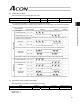
77 b LEAD Ball screw lead [mm] -
Set individually in accordance with
the actuator characteristics.
78 b ATYP
Axis operation type -
Set individually in accordance with
the actuator characteristics.
79 b ATYP
Rotation axis mode selection -
Set individually in accordance with
the actuator characteristics.
80 b ATYP
Rotation axis shortcut selection -
Set individually in accordance with
the actuator characteristics.
88 a SWLM
Software limit margin mm
Set individually in accordance with
the actuator characteristics.
91 b PSFC
Current-limiting value at stopping due to missed
push-motion
-
0 [Current-limiting value during
movement]
* The numbers are displayed on the PC software screen but not on the teaching pendant.
The missing numbers are not used and omitted.
The category codes are provided only for convenience and not displayed on either the PC software screen or
teaching pendant.