
Manual


53
4. Operation Using I/O Signals
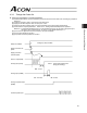
(2) Command Pulse Mode
User Parameter No. 63 (Command-pulse input mode)
Name Symbol Unit Input range Default (reference)
Command-pulse input mode MOD - 0 ~ 2 1
Set a pulse-train input pattern for command pulse input (PP•/PP, NP•/NP).
* The setting of positive logic or negative logic is explained in (3), “Input Polarity in the Command Pulse Mode.”
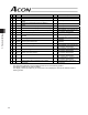
(3) Input Polarity in the Command Pulse Mode
User Parameter No. 64 (Polarity in command-pulse input mode)
Name Symbol Unit Input range Default (reference)
Polarity in command-pulse input mode POLE - 0 ~ 1 0
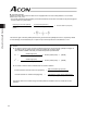
Setting
Positive logic: 0
Negative logic: 1
Command-pulse
input pattern
Input terminal Forward Reverse Setting
Negative logic
Positive logic
Forward pulse train
Reverse pulse train
Pulse train
Sign
Phase-A/B
pulse train
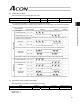
Forward pulse trains indicate motor revolutions in the positive direction, while reverse pulse trains indicate motor
revolutions in the reverse direction.
Command pulses indicate motor revolutions, while the sign of the command indicates the rotating direction.
Phase-A/B x4 pulses of 90q phase difference indicate both revolutions and rotating direction.
Forward pulse train
Reverse pulse train
Pulse train
Sign
Phase-A/B
pulse train