
Manual

35
4. Operation Using I/O Signals
4.2 Standard Mode
Choose the PIO pattern of this mode if you wish to perform position control using pulse train input from a PLC.
Set User Parameter No. 25 (PIO pattern selection) to “0.” (This parameter has been set to the “standard type” prior to
the shipment).
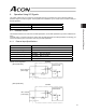
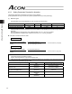
4.2.1 Explanation of I/O Signals
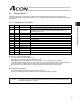
Pin No. Signal Name Remarks
1 24 V External 24 V
2 0 V External ground
If the controller is used in the open collector mode, also use this pin for the
COMMON signal for command pulses as well as the 0V signal for the
controller’s control power.
3 IN0 SON Servo-on signal
4 IN1 TL Torque-limit selection signal
5 IN2 HOME Homing signal
6 IN3 RES Reset signal
7 OUT0 SV Servo-on output
8 OUT1 INP Positioning complete signal
9 OUT2 HEND Homing complete signal
10 OUT3 *ALM Alarm signal
11 /PP Command pulse
12 PP Command pulse Not connected if the controller is used in the open collector mode.
13 /NP Command pulse
14 NP Command pulse Not connected if the controller is used in the open collector mode.
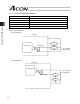
Servo-on Command Input (SON)
The servo remains on while this signal is ON.
The actuator can be operated while the SON signal is ON.
While this signal is OFF, the actuator does not operate even when the controller power is supplied.
If the SON signal is turned OFF while the actuator is operating, the actuator will decelerate at the forced-stop torque
until it stops. After the actuator stops, the servo will turn off and the motor will enter a free-run state.
At this time, the function specified by the applicable parameter (electromagnetic brake) becomes.
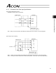
Reset Signal Input (RES)
This signal resets the alarms currently detected by the controller.
You can turn the RES signal ON to reset the alarms currently detected by the controller.
Caution: This signal cannot reset cold-start level alarms. Identify the cause of each alarm and remove the
cause before restarting the controller.